At the outset it should be realized that the Dominys' tools were used to produce goods. Nathaniel
Dominy IV, Nathaniel V, and Felix needed their tools in their work; they were not
using them in an avocation or as an outlet for artistic innovation. These statements are not
intended to give the impression that the Dominys derived little pleasure from their work or
that they were not interested in producing aesthetically pleasing objects. But the main purpose
of these tools was to enable the Dominys to earn a living, to support their families, and,
if possible, to advance socially, as well as economically, in their society.1
The number and variety of tools the Dominys used for woodworking and clockmaking leave
no doubt that their shops were self-sufficient and capable of turning out a wide variety of
products. The shops were true "manufactories" in which the craftsman was competent to perform
each operation and produce a finished piece. There was no division of labor, no assembly-line
production, and the Dominys powered their tools by human muscle. The survival of so
many of the tools used between 1760 and 1840 by three generations of this East Hampton family
gives a picture of well-stocked craft shops of the eighteenth and early nineteenth centuries.
Such shops, however, disappeared in the second quarter of the nineteenth century with the
transition from craft to factory production and its resultant need for new types of tools. Peter
Welsh, a member of the staff at the Smithsonian Institution, has described the efforts of
nineteenth-century patentees as the "quest for multipurpose solutions through the perfection
of the combination tool."2 The nineteenth-century factory hand was often a specialist who
took his tools to work with him. His tools, therefore, had to be portable and "multipurpose."
He could not have carried the number of tools the Dominys found indispensable, nor would
there have been a place to house them on the job. The factory age brought the development
of the versatile tool as it spelled the decline of the handcraftsman.
The Dominys were not unique either in their shop operations or in the tools they used.
That much is evident in the craft shops from rural areas which have been restored or reconstructed
in a number of American museums. There were other country craftsmen who practiced
as many different trades as the Dominys and who undoubtedly had a great variety of
tools on hand. On August 18, 1763, for example, the Maryland Gazette, published at Annapolis,
carried the sale notice of a rural woodworking establishment rivaling that of the Dominys:
"To be sold…for the use of the Orphans of Richard Taylor, Deceased . . . [at his dwelling
at the] head of South River…Carpenter's, Cooper's, Joiner's, Wheelwright's, and
Turner's Tools." The reconstruction of Anthony Hay's cabinet shop by Colonial Williamsburg
represents a craft establishment in an important eighteenth-century town. Its appearance
derives from careful archaeological work during which artifacts were discovered preserved in
p. 32
clay silt. Research indicates that, like the Dominys, Hay may have done metalworking to
supplement his cabinetmaking income. However, only some forty-odd fragments of his tools
were found as compared to the more than one thousand tools preserved by the Dominy
family.3
The Dominy Tool Collection, because it is almost complete, can serve as an index to the
equipment used by city as well as country craftsmen. Tools in the shops of both urban and
rural artisans were identical and quite often came from the same source—England.4 As the
following list shows, nearly every joiner's tool imported in 1760 by William Wilson, of Philadelphia,
had a counterpart in the Dominy woodworking shop.
Philada
List of a Chest of Joiners Tools to be Shipt pr William Neale for accot of Wm Wilson (being
for Richard Johns).
12
Pair of Hollows and Rounds
[Cf. Nos. 71, 72, 89]
1
Oge [ogee] of 4/8
[Cf. No. 77]
2
Astricles [astragals] One 4/8 the other 6/8
[Cf. No. 61]
2
Picture frame Planes
2
Bead Planes, one 8 the other 3/16
[Cf. Nos. 61, 62]
3
Rabbit Plains viz One 1½ In [ches] escou [skew] the others square One an Inch, the other ½ Inch
[Cf. Nos. 83, 85, 86]
1
Side Rabit Plain
[Cf. No. 84]
1
Astrical & hollow to work in Quirk 1⅛in on
1
Moving Filister without Arms
1
Left handed Fillister of 2/8
2
Pair of Groving Planes with the Tongue brass, the one 4/8 the other 6/8
[Cf. No. 81]
1
Plow with 2 Set of Irons
[Cf. No. 81]
1
Sett of bench Plains wth a jointer
[Cf. Nos. 69, 70, 73, 74, 80]
1
Half Upright Foreplain & Smoothing Do
[Cf. Nos. 92–94]
1
Strike block & one tooth plane wth 2 Irons of different Cut
1
Stock with 1 Set of Gouge, 1 of Center & 1 of Alis' [the maker] Nose Bitts
[Cf. Nos. 12, 15, 20]
1
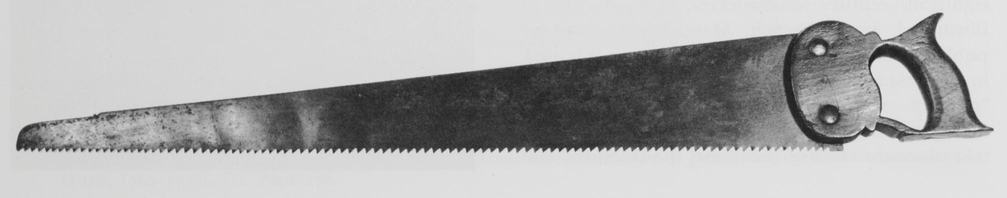
handsaw 2feet 2½in long
all of white's [the maker's] best sort with a good Saw Sett
[Cf. No. 104]
1
Panel Do same length
1
Tenant Saw
[Cf. No. 101 ]
1
Sash Saw
6
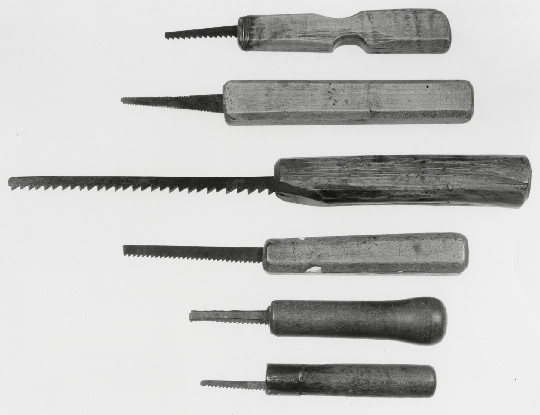
Small key holedo
6
small key hole saws
[Cf. No. 105]
8
Mortois [mortise] Chizells
[Cf. No. 24]
12
broad & narrow Firmers
[Cf. No. 24]
12
broad & narrow Gouges with the Steel the Inside
[Cf. No. 40]
2
Scribing Gouges with the Steel the out Side of ⅜ & ⅝
[Cf. No. 40]
3
doz Moores [maker] best plain Irons 2 @ 2½ In.
3
doz Handsaw Files fine cut
[Cf. No. 33]
1
Pair Pinchers
[Cf. No. 60]
1
Pair of Nippers for Cutting Wier [wire]
1
Joiners Hatchet
1
Turkey Stone Clear of Knotts
Let the Beach [beech] be well seasond the chizels & gouges be handled, The plains in good p. 33
order – Let all things be of the best & the Chest neatly fitted – Let the planes be of John Ridgus's [Ridge's?] make [.]5
The same kinds of tools as those owned by the Dominys were also used by Jeremiah Cresson,
a Philadelphia cabinetmaker whose Chestnut Street shop stood near that of his well-known
colleague Benjamin Randolph.6
Some writers hold that urban craftsmen used imported tools, while rural artisans either produced
their own or had them made locally.7 To some extent this may be true, but it is much
more likely that geography and the practices of a rural economy were the determining factors.
Craftsmen in both cities and villages whose shops were located near navigable water probably
received the cheaper and well-made English imports directly from overseas or by transshipment
from major ports. Although there were toolmakers at work in America during the
eighteenth and early nineteenth centuries, their products never seriously rivaled those of European
manufacturers.8 Transportation costs for the overland movement of goods in the United
States prior to 1840 were so high that they almost prohibited the distribution of American-made
tools. The report of a United States Senate committee written in 1816 indicated that
"a ton of goods could be brought 3,000 miles from Europe to America for about nine dollars,
but…for the same sum it could be moved only 30 miles overland in this country."9 In
the same year A. J. Dallas, Secretary of the Treasury, reported to Congress that hardware,
ironmongery, and cutlery were in a class of "manufactures which were so slightly cultivated
as to leave the demand of the country wholly, or almost wholly dependent upon foreign
sources for a supply."10 Moreover, the American craftsman's attitude toward locally made
tools may have been typified by a turner who advertised the loss of "a parcel of turning tools"
in the July 1, 1732, issue of the South-Carolina Gazette. "The Turning Tools," he said, "were
made in this country, and are very clumsy, and may be known by that."11
There is ample evidence in both the Dominy manuscripts and the tool collection that English
tools were brought from New York City to East Hampton in ships plying Long Island
Sound. In 1765 Nathaniel Dominy IV purchased a number of tools from Aaron Isaacs, who
sailed weekly between East Hampton and New York.12 They may have been replacements for
worn or broken tools originally used by Nathaniel's father. The list of these purchases included:
His brother John (1760–1837) brought "2 large files at ⅔" and "2 small do at 8d" in a
group of "Sundrys yt you bot for me at N. York" in February 1789.14 Tools were often sold
"at vendue," and "an ax" was acquired in 1798 in that manner from Joseph Osborn, Jr.,
at a cost of "5/1."15
The references in early accounts to files, plane irons, saws, gimlets, and hammers may indicate
that Americans imported only the metal parts of tools from England and the Continent
and fitted them with handles of their own making. In the Dominy Collection, for example,
the tools bearing marks of London, Sheffield, and Warrington makers but having handles or
stocks of American wood outnumber those with mounts of English or European wood. The
English mounts are of beech, European ash, birch, or boxwood. Moreover, we should remember
that when William Wilson ordered tools from England for Richard Johns he stipulated
that "the Beach [beech] be well seasond the chizels & gouges be handled." Many catalogues
of English tools advised that boxwood, birch, ash, or beech handles could be supplied with the
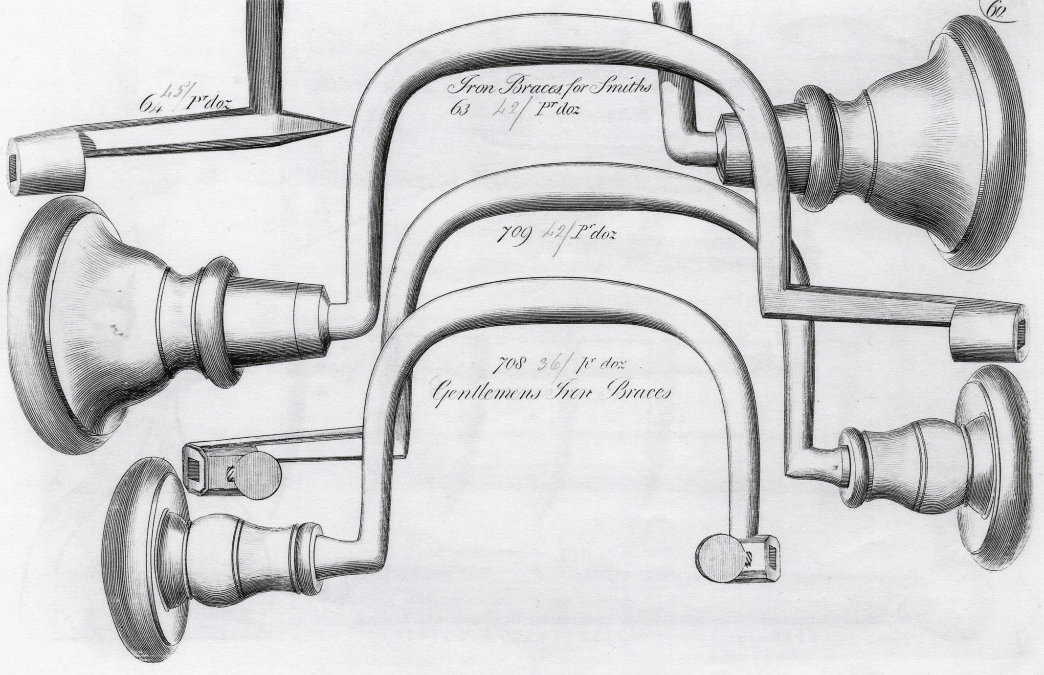
tools pictured. Planes, bevels, braces, squares, and saws are illustrated in some pattern books
with the wood parts attached, although the woods are not usually identified.16
Some of the Dominys' tools were acquired from or repaired by local blacksmiths, probably
because it was the only way they could pay for services rendered to them by the Dominys.
Whether blacksmiths actually made some of the tools listed in the accounts is uncertain, except
when the entry is preceded by the word "forgeing." These account books show, however,
that East Hampton artisans supplied the Dominys with a variety of items as follows:
Their customers often paid debts with tools. Payments included two files from Joseph Ellis
in April, 1768; a plane iron from Nathan "Conking" (Conkling) in 1770; six gimlets from
"Isaac Barns Esqr" in May, 1770; two "gimblets" from Abraham Miller, 1773; three large
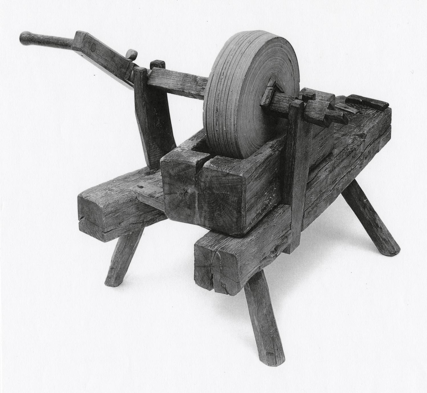
files from Herbert Latham 1786; a saw from Sylvester Dearing in 1790; a "Grin[d]stone"
from Jeremiah Miller, 1791 (No. 42); two small files from Jonathan Sizer in 1792; and a
"Double Iron Jack Plain" from Miller Dayton in 1808.25
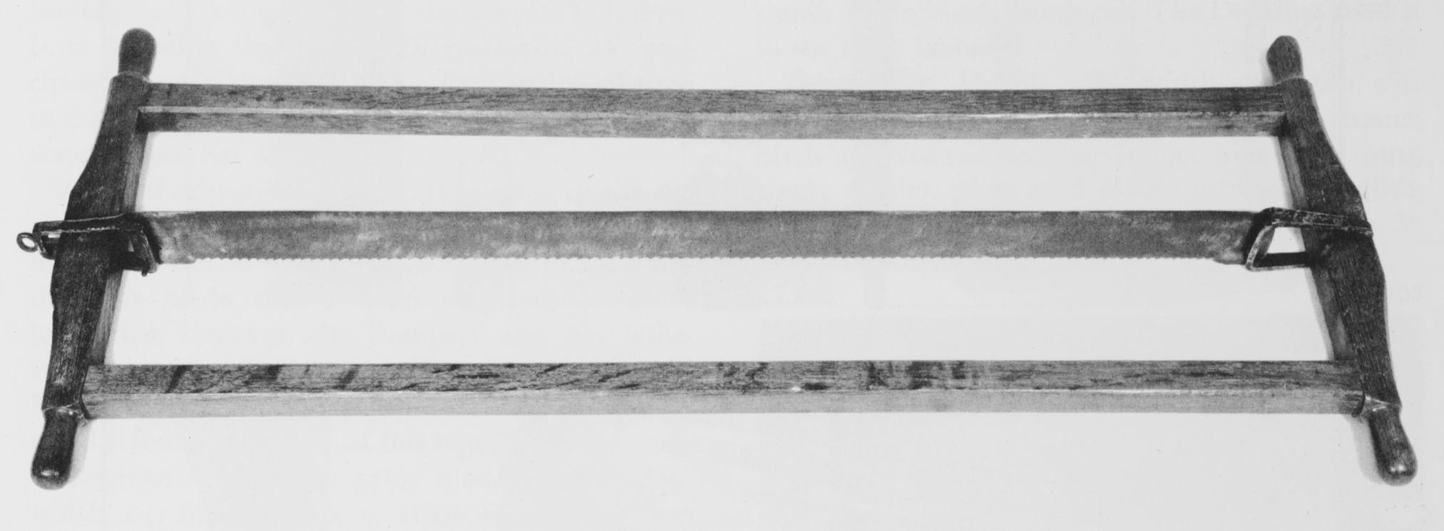
At least one important tool, a whipsaw, was owned by the Dominys in partnership with
other local craftsmen. On September 29, 1794, Nathaniel Dominy IV paid Jonathan Conkling
14 shillings for a quarter share "of the Whip Saw which was ownd in Co[mpany]," and on the
same day he bought Abraham Mulford, Jr.'s half share for £1 8s. Unfortunately, that saw,
used to cut trees into logs of manageable size for hauling, has not survived.26
The Dominy manuscript records and the tools pictured in Chapter IV show a constant flow
of new tools into the Dominy shops and an equally constant conversion of worn-out tools into
new and useful implements from the 1760's on. In cataloguing the tools for display in the reconstructed
shops, the problem of eliminating tools acquired by Nathaniel Dominy VII between
1850 and 1900 arose. When these early mail-order examples were marked by the manufacturers,
dating them was usually not difficult; it developed, however, that names were not a
reliable index because many eighteenth- and early-nineteenth-century toolmaking firms continued
production into the twentieth century.27 As a result, the type of stamp used, its form,
and the style of the lettering often proved to be more important than the name itself.
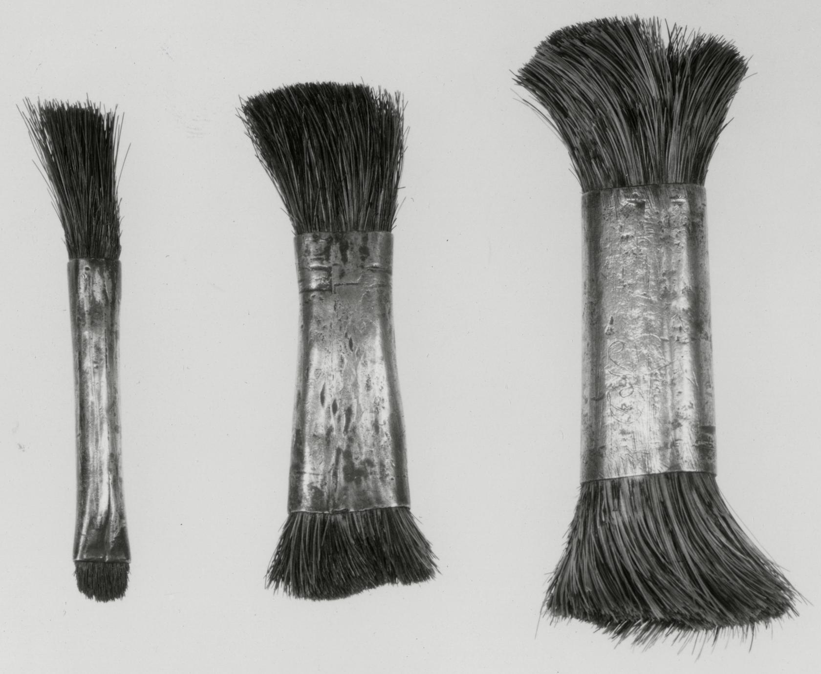
The shape of a tool, its design, and the presence or absence of decoration were also important
clues used in establishing the date of some of the Dominys' implements. It was generally
found that the more decorative and ornamental tools were of early origin. As toolmaking by
p. 37
machines and specialists advanced, there was a consequent stripping of the design to basic essentials.
The machine age destroyed the reflection of the toolmaker's personality; the simple
aesthetic flourishes he usually added to his products in the form of notches, cyma and other
curves, and chamfered edges vanished forever. All these personal touches can be seen in the
Dominy tools illustrated in Chapter IV.
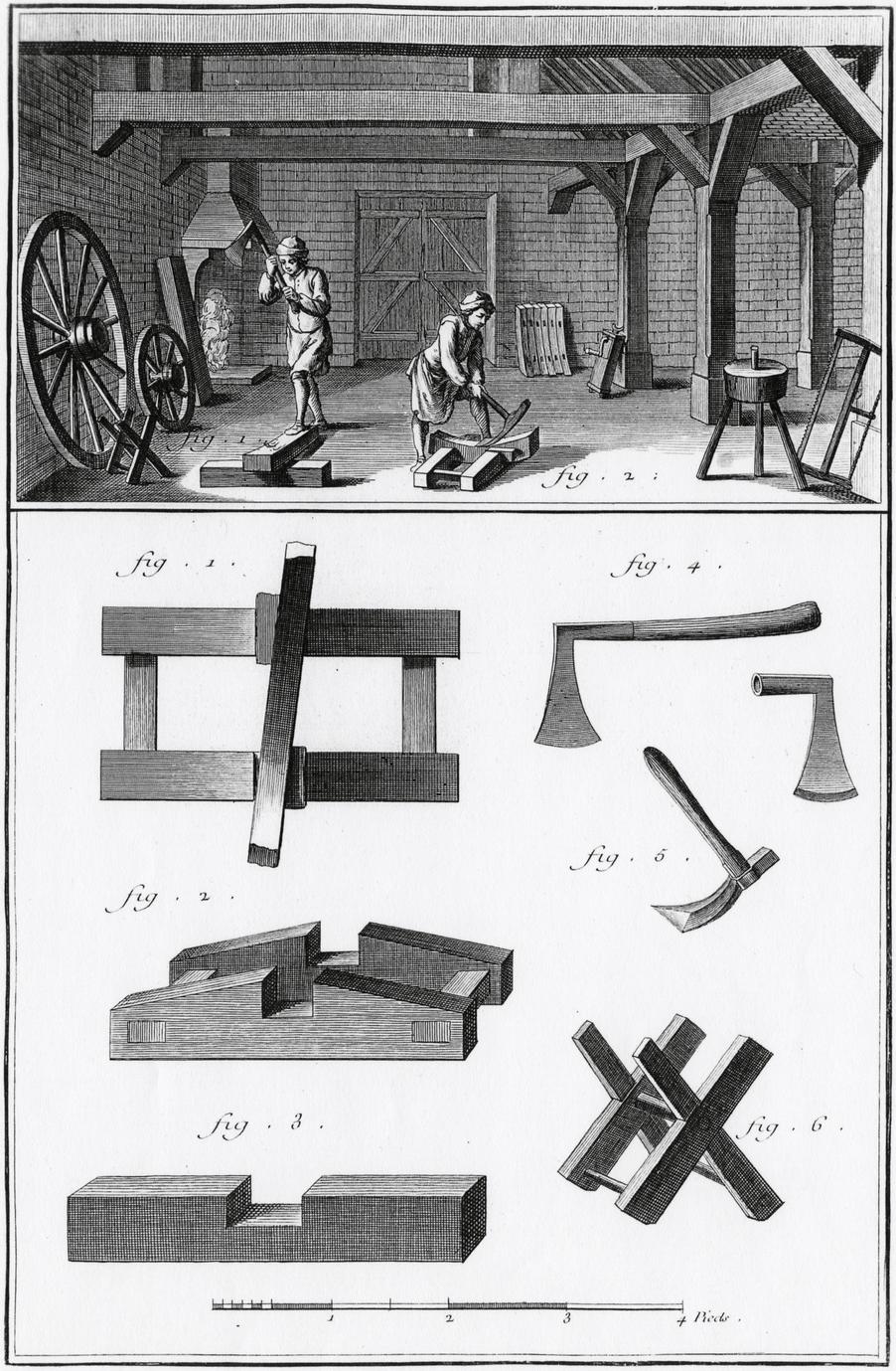
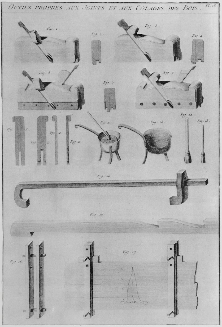
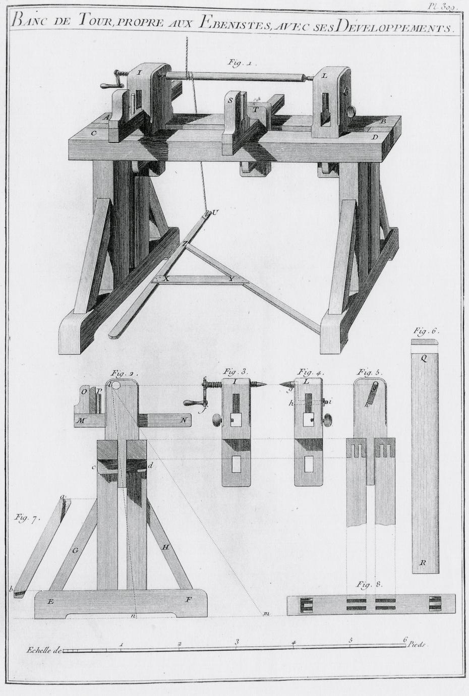
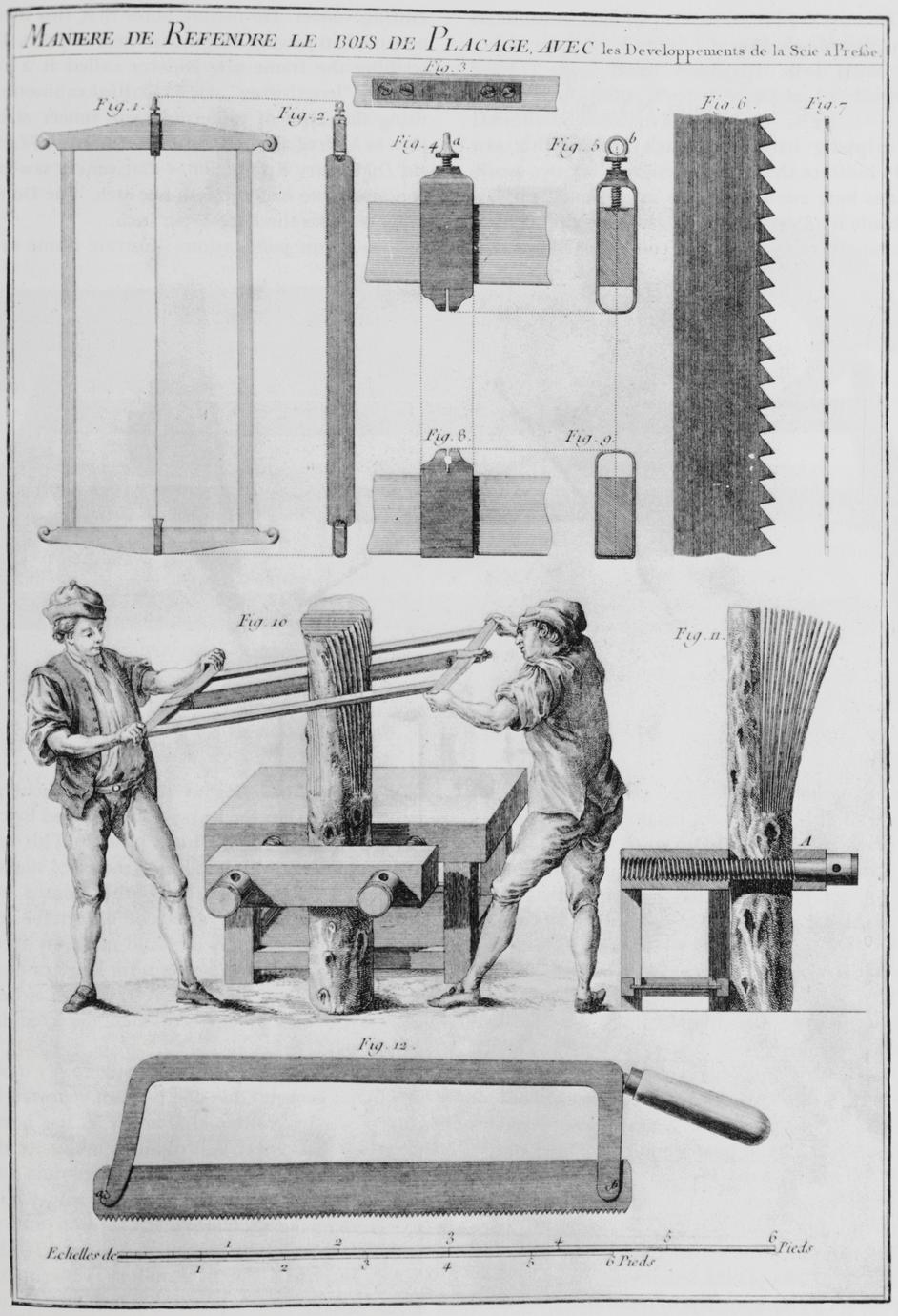
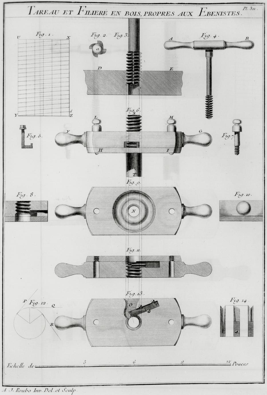
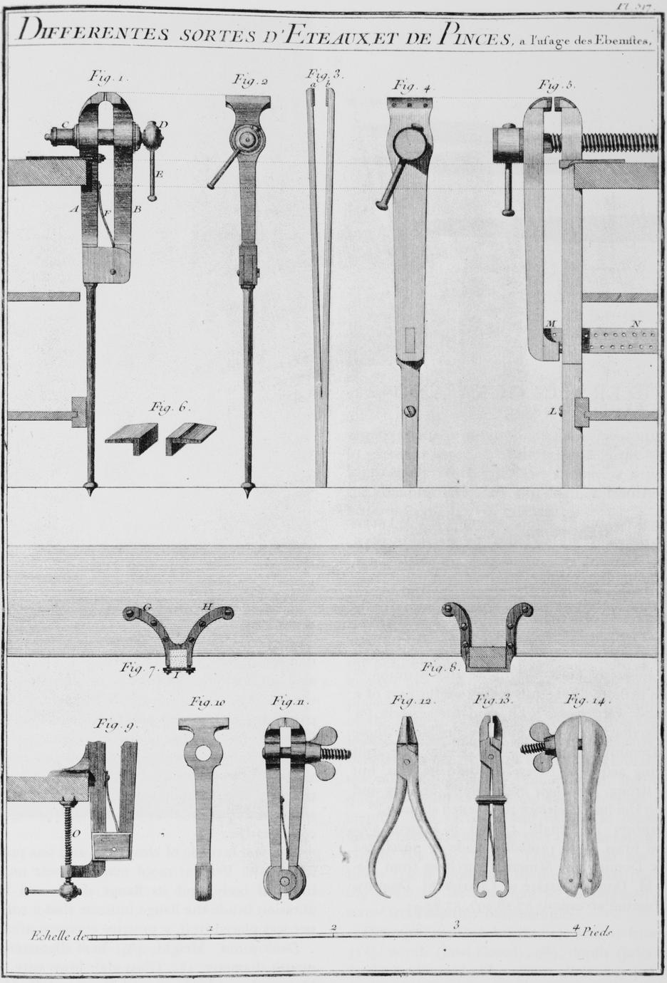
A third important resource used in dating the Dominy tools was the illustrations in such
eighteenth-century books as Denis Diderot's Encyclopédie, André Jacob Roubo's L'art du
menuisier, and other volumes of the Descriptions des arts et métiers published by the Académie
Royale des Sciences, as well as tool catalogues circulated by English toolmakers or distributors
in the late eighteenth or early nineteenth century.28 When the Dominy tools were compared
with those pictured, it was discovered that, although these craftsmen did not have access
to the contemporary dictionaries of craft technology, many of the tools and processes used
by Nathaniel IV, Nathaniel V, and Felix were remarkably similar to those illustrated in the
books mentioned above (see Nos. 9, 19, 27, 39, 46, 49, 101–3, 107, 121, 132, 169). Perhaps no
better evidence than this exists for establishing the universality of craft techniques and equipment
in the Western world at a time when the "art and mystery" of individual crafts were
passed on to succeeding generations through the apprentice system. The great French and,
by comparison, minor English encyclopedias were compendiums of the experience and technical
knowledge accumulated over the years; they mirrored the skills that master craftsmen
of the "Atlantic Civilization" passed on to their apprentices or sons.
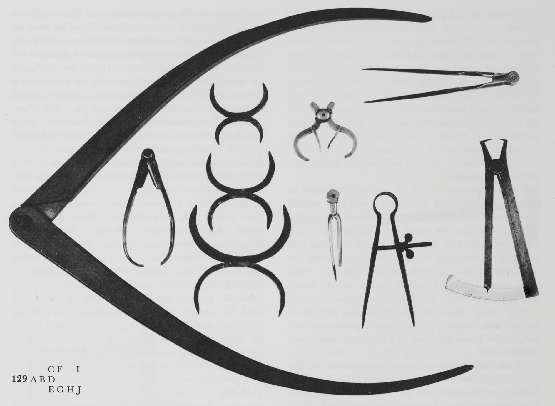
Dating a tool by its shape alone is not a reliable method unless the assigned date spans many
years. The changes that have taken place in the design of hand tools have been subtle and undramatic
and have occurred over a long period of time. The snail's pace at which hand tools
have evolved through the centuries will not be reviewed here since it is documented in W. L.
Goodman's The History of Woodworking Tools, Henry C. Mercer's Ancient Carpenters' Tools, and
in several articles in A History of Technology, edited by Charles Singer et al.29 In considering
form as an evidence of date, a human characteristic must also be taken into account. George
Kubler points out in The Shape of Time that men do not discard familiar objects easily: "When
the industrial designer discovers a new shape to satisfy an old need, his difficulty is to find
enough buyers for the new shape among people who already own satisfactory old forms."30
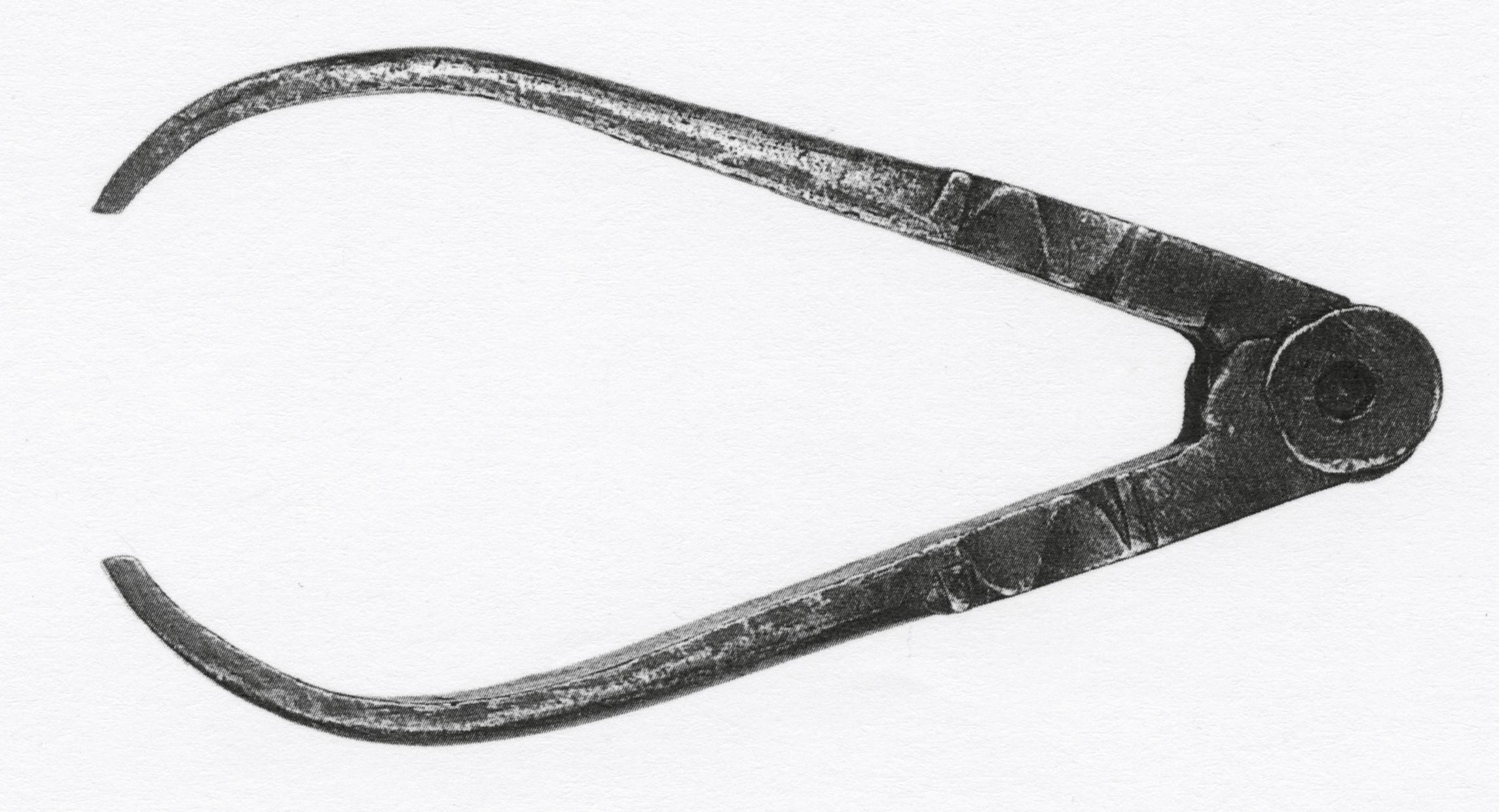
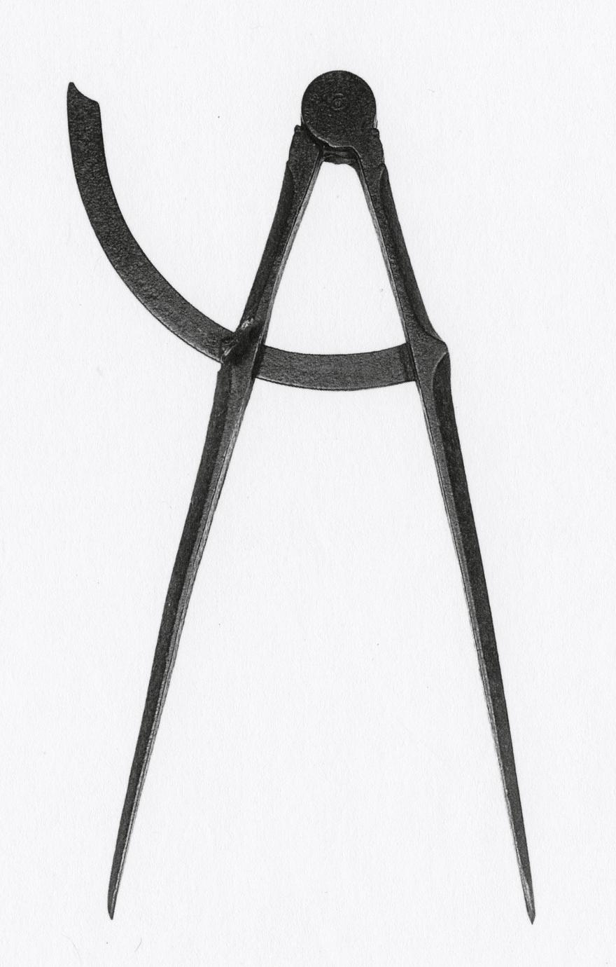
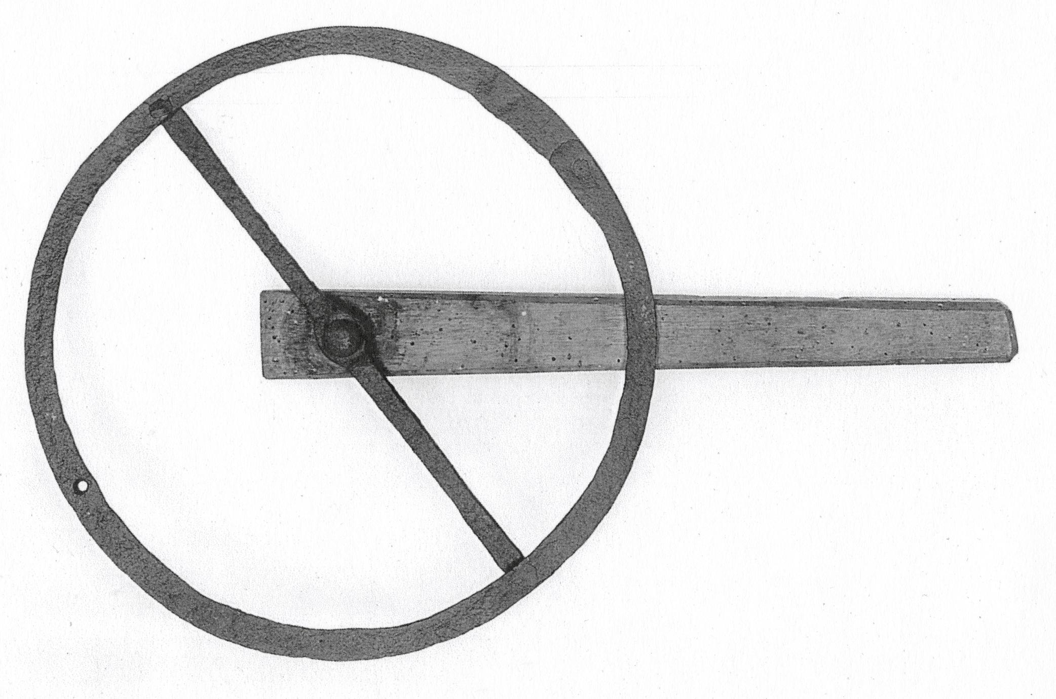
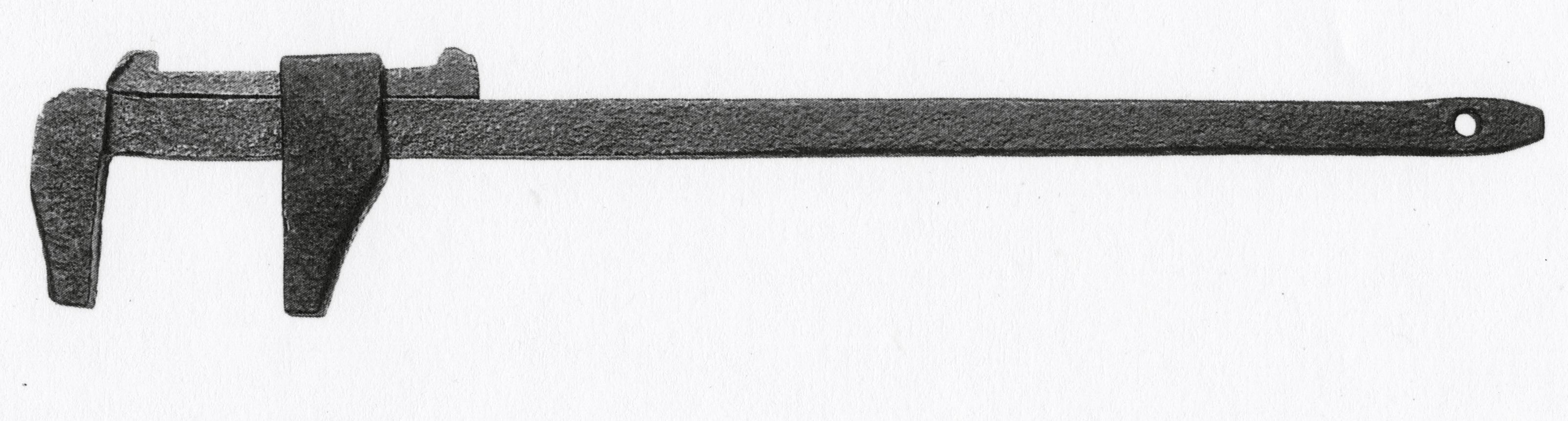
This principle is well illustrated by the calipers (No. 129J) probably purchased by Nathaniel
Dominy VII between 1850 and 1860 and almost identical to a pair shown in a catalogue of
craftsman's tools published in 1965. Still another factor must be considered in connection with
form. During the period when the Dominys were active, it was easier to repair or convert tools
than it was to purchase new ones. Thus, in the Dominy family manuscripts there are numerous
references to new layers of steel put on the cutting edges of worn chisels and axes and to the
conversion of old file blades into turning chisels, screw taps, and brace bits. It must be remembered,
too, that after 1790 two Dominy craftsmen worked in the shops and that new tools
ordered were only slightly, if at all, different from those already at hand. Obviously, dating
tools by shape alone must be done with great caution.
Although a recent author has developed a chronology of changes in the shapes of tool handles,
p. 38
his findings are not substantiated in the Dominy Collection.31 Careful study of the latter
shows that when handles and other wooden parts of tools used by early Dominy craftsmen
were replaced by later members of the family, they sometimes made the new part very plain;
at other times they patterned it directly after the original. There are also some instances in
which a handle in good condition was removed from the worn part and refitted with a new
metal blade. In both instances the researcher is confronted with handles and metal parts of
different dates.
There is some evidence to support the theory that the shapes of handles and tools were influenced
by the preferences of local or regional craftsmen. The Museum of English Rural Life,
Reading, Berkshire, has manufacturers' catalogues and manuscripts which give the choices
for agricultural tools in various localities. In 1863 the Douglas Axe Manufacturing Company
published the Price List and Illustrated Patterns of axes and other edge tools made at its East
Douglas, Massachusetts, factory. That the products were designed with local customs, lumbering
practices, and types of trees to be cut in mind is suggested by the offering of slightly different
versions of the felling ax with a heavy poll for "Kentucky, Ohio, Yankee [New England?],
Maine, Michigan, Jersey, Georgia," and "North Carolina." Broadaxes were shown in
patterns for "New England, New Orleans, Ohio & Western," and "Pittsburgh." A recently
published picture of three try-plane handles made between 1750 and 1800 in different parts
of Europe shows marked differences.32 Therefore unless the history of a tool, its original owner,
and subsequent owners are known, only very general date ranges can be assigned to tools on
the basis of handle designs.
The Dominy Collection is important because of its size; it is unique because the tools were
owned and used by people whose life spans, working habits, purchases, customers, and shop
sites are known. Thus research can be carried on within narrower limits than is usually possible.
In the study of tool dating, however, it is the craftsmen themselves who have made the
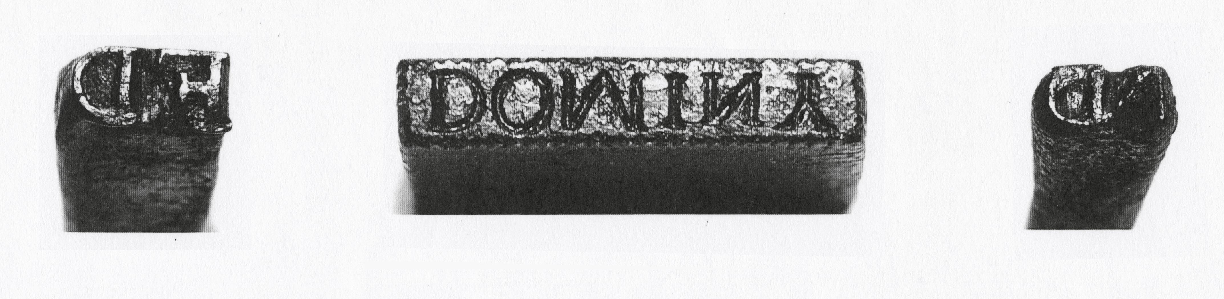
collection of inestimable value: the Dominys marked some of their tools with manufacture or
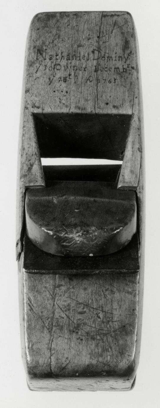
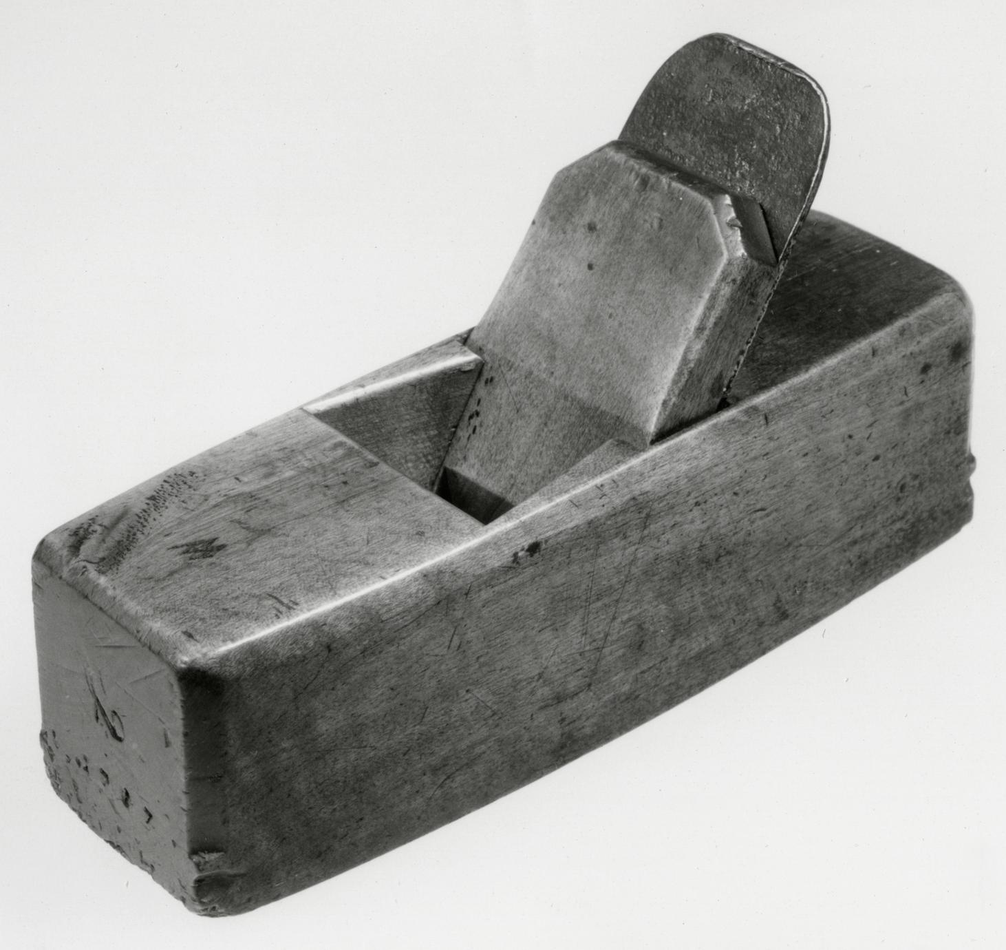
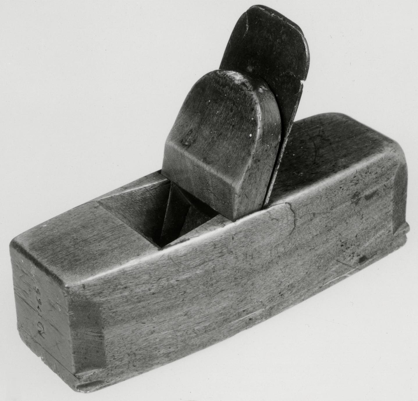
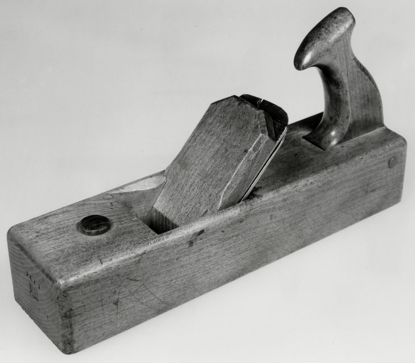
acquisition dates plus the initials or the name of the owner. Forty-seven planes (ranging in
date from 1765 to 1817), two marking gauges, a brace, a bevel, a yardstick, a square, a container
for polishing compound, and a shotmold—a total of fifty-five articles—carry the date
of manufacture or acquisition. At least fifty-nine others are stamped ND (Nathaniel Dominy
IV), DOMINY (Nathaniel Dominy V), or FD (Felix Dominy). This makes it possible
to establish when the unmarked Dominy tools were made by comparing them not only with
illustrations in encyclopedias and tool catalogues but with dated examples used by the craftsmen
during their working years.
In the following chapter the catalogue of the Dominy tools is divided into two sections, one
describing the tools used in woodworking and the other those used in metalworking. It is
obviously impractical to illustrate all of the one thousand tools. Instead, one or more representative
examples are shown in categories which are arranged alphabetically. This system is
contrary to Mercer's classification in Ancient Carpenters' Tools, where the categories are determined
by function or purpose, and to S. C. Wolcott's modification of Mercer's method,
with groupings by function, craft, and age.33 Because the Dominys practiced such a variety
p. 39
of crafts and used the same tools for so many different purposes, neither of the established classification
systems could be applied. All dimensions are given in inches; the identification of the
woods used in the tools is the result of microanalysis by Gordon Saltar, who is a specialist in
the identification of wood samples at The Henry Francis du Pont Winterthur Museum. Woods
used for the tools illustrated proved to be as expected, hickory (64) being by far the most
common tool handle, followed closely by soft maple (48). An amazing variety of woods was
used for tool parts by these rural craftsmen: cherry (17), beech (16), dogwood (14), white oak
(10), birch (9), white pine (8), apple (7), Ceylon satinwood (6), red oak (6), tulip (5), boxwood.
(5), ash (4), pear (3), and mahogany (2) were found as well as one instance each of
white cedar, black gum, hard pine, Australian rosewood, lignum vitae, and European yew.
The appearance of Ceylon satinwood was rather a surprise, but its presence in tools used by
the East Hampton craftsmen was confirmed by analysis of the stocks of three smoothing planes
and a hollow plane. Two of these Ceylon satinwood planes are dated 1765. The most popular
wood for plane making was, as expected, beech (31). Other woods of which plane stocks in
the Dominy Collection were made include birch (17), cherry (3), soft maple (3), and white
oak (1).
One question not answered by the Dominy Tool Collection is this: How many tools of each
type were needed in an eighteenth- or early-nineteenth-century craftsman's shop? Because
there are no inventories of the estates of two of the Dominy craftsmen, it is impossible to discover
how many tools were in the shops when Nathaniel IV died in 1812 or when Nathaniel V
died in 1852. At the time of his death in 1868 Felix had been removed both from craft activity
and from East Hampton for thirty-three years. The inventory of his estate contains no mention
of the tools. Any attempt to reconstruct a list of the equipment which stood in each shop
at a given time is practically impossible because the working dates of father and son overlap.
This overlap particularly clouds establishment of the precise work location of unmarked
tools.34
Compounding the problem of establishing the shops' original inventories is the knowledge
that some tools vital to the Dominys' craft production have not survived. From the lists of
tools purchased in New York and acquired from local smiths, cited above, it is known that the
Dominys owned hammers, broadaxes, and a hatchet acquired in the eighteenth century; if
these exist today, their whereabouts is unknown. In the collection, however, are nineteenth-century
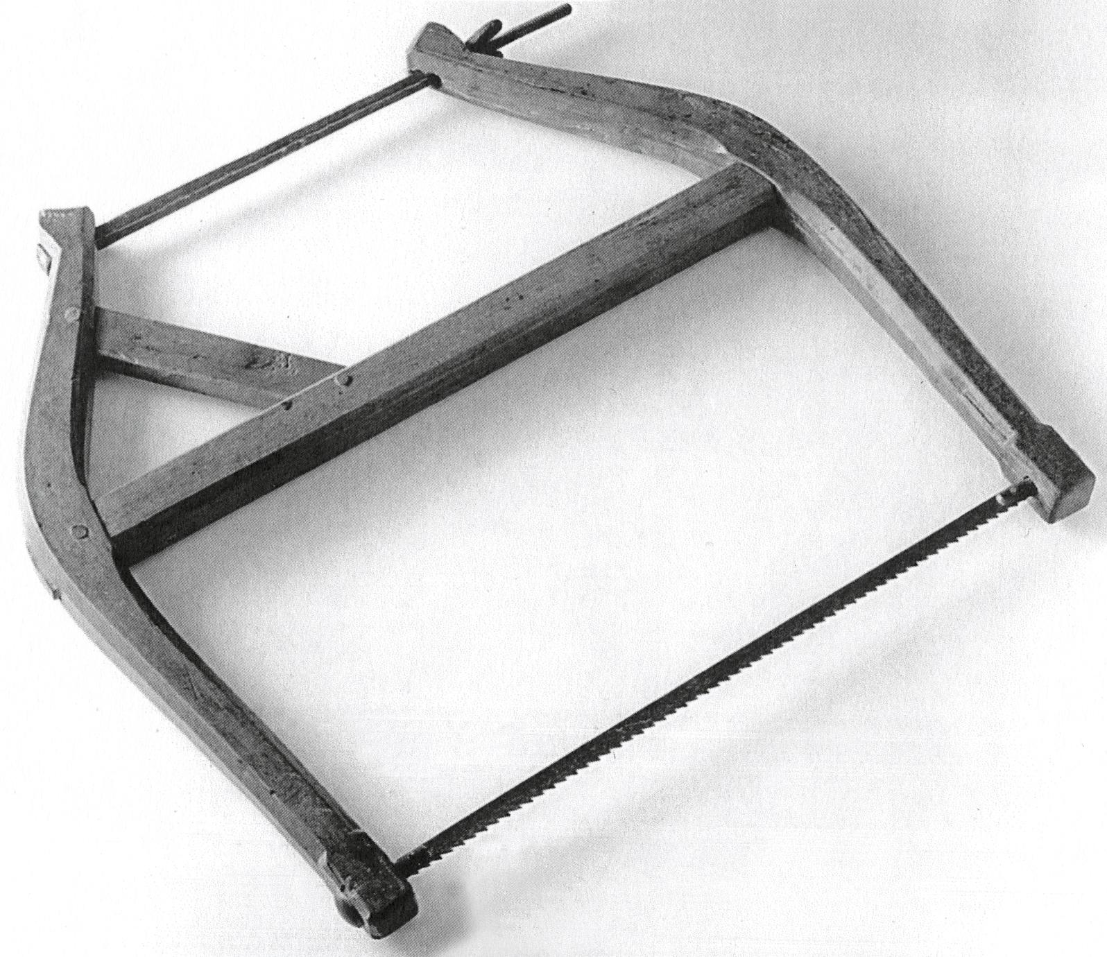
broadaxes, purchased after the earlier ones became worn. A cabinetmaker's bow saw
larger than the one now seen at Winterthur would have been essential, as would the whipsaw
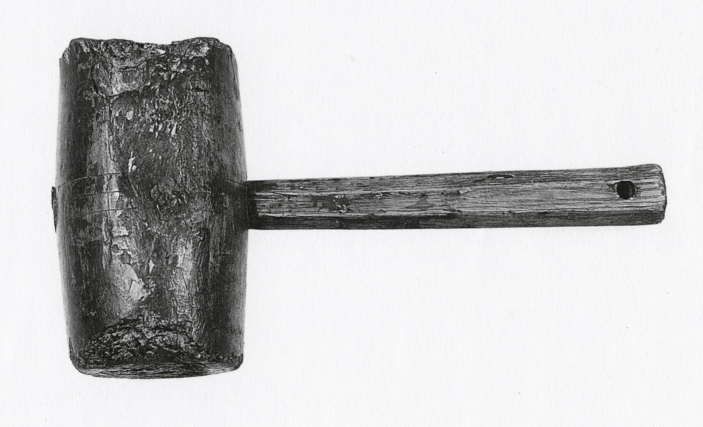
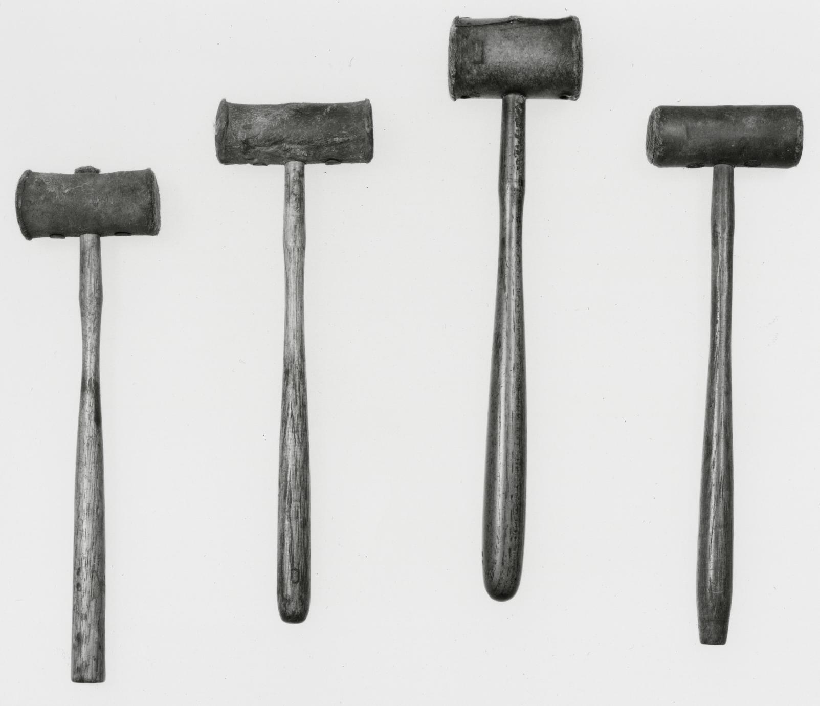
Nathaniel IV owned. Mallets were necessary tools, but they wore out quickly; undoubtedly
there was a predecessor of the late-eighteenth- or early-nineteenth-century one seen in the
collection today. For the reasons just given and in the interest of accuracy, the tools discussed
in Chapter IV are presented as examples of those actually used by the Dominys rather than
as a complete picture of their shop equipment.
Many of the tools illustrated in the catalogue bear the stamp CAST STEEL on the blades.
The stamp identifies the metal in the tool. It does not indicate a manufacturing process by
which objects are cast into shape. "Cast," or crucible, steel was "more homogeneous in composition
p. 40
and more free from impurities" than other steels. It was made by melting steel in air
furnaces and then casting the steel into ingots. Tool blades were later tempered and shaped
from pieces of the cast-steel ingot. Benjamin Huntsman (1704–1776), an Englishman of Dutch
descent, perfected the process early in the eighteenth century, but Sheffield firms and other
English manufacturers considered cast steel too hard and did not adopt it widely until the
very late eighteenth or early nineteenth century.35
Unless otherwise indicated, all the tools listed in Chapter IV were purchased with funds
provided for that purpose by Henry Belin du Pont.
Notes
1 The best summary of the craftsman's goal of work as
a way to become a merchant capitalist is found in Louis
B. Wright, The Cultural Life of the American Colonies,
1607–1763 (New York, 1957), pp. 23, 28.
2 "United States Patents, 1790 to 1870: New Uses for
Old Ideas," United States National Museum Bulletin
241: Contributions from the Museum of History and
Technology, Paper 48 (Washington, D.C., 1965), pp.
124–25.
3 Carlisle H. Humelsine, The President's Report
[Colonial Williamsburg, Inc.], 1960 (Williamsburg, Va.,
961), pp. 3–30.
4 Charles F. Hummel, "English Tools in America: The
Evidence of the Dominys," Winterthur Portfolio, II
(1965), 27–46.
5 Letter and Order Book, William Wilson, Philadelphia,
1757–1760, DMMC, Microfilm 847; original manuscript
in the New York Public Library. Moores best plane irons
were made by Robert Moore, a London and Birmingham edge
tool maker, ca. 1745-1775, identified by W.L. Goodman,
letter to the author, December 31, 1975. In the same
letter, Goodman identified ‘John Ridgus’ as John Rogers,
planemaker in Tufton Street, Westminster, London, 1734-1765
6 A complete list of tools sold by Cresson at his retirement
is found in the Pennsylvania Packet (Philadelphia),
March 15, 1779, as quoted in Alfred Coxe Prime,
comp., The Arts & Crafts in Philadelphia, Maryland,
and South Carolina, 1721–1785 (Topsfield, Mass., 1929),
p. 164.
7 Carl Bridenbaugh, The Colonial Craftsman (New
York, 1950), p. 41.
8 Hummel, pp. 29–35.
9 Quoted in George Rogers Taylor, The Transportation
Revolution, 1815–1860, Vol. IV of The Economic
History of the United States (New York, 1951), pp.
132–33.
10 Quoted in J. Leander Bishop, A History of American
Manufactures from 1608 to 1860 (Philadelphia,
1866), II, 221–23.
11 As quoted in Prime, p. 187.
12 Probably Aaron Isaacs, Sr. (1722/23–1797/98), because
Aaron Isaacs, Jr. (1752–1815), would have been
too young to warrant so much mention in the Dominy
accounts. See Rattray, EHH, p. 405.
13 Account Book B, Nathaniel Dominys IV and V,
1762–1844 (DMMC, MS 59x9a), pp. 100, 105.
14Ibid., p. 109.
15Ibid., p. 47.
16 For an example, see Joseph Smith, Explanation or
Key, to the Various Manufactories of Sheffield (Sheffield,
Eng., 1816).
17 A term used to describe the placing of a new steel
edge or facing on an old tool. See Definition 36, The
Oxford English Dictionary.
18 Account Book B (DMMC, MS 59x9a), pp. 3, 47.
19 "The latch of a door or gate; the lever which raises
the bar of a latch; a catch" (OED).
p. 41
20 A colloquial expression for snipebill; "the bolt connecting
the body of a cart with the axle" (OED).
21 Account Book B (DMMC, MS 59x9a), p. 60.
22 Probably refers to bickern, bickhorn, or beak-iron;
the tapered end of an anvil or an anvil with such a
tapered end (OED).
23 Account Book B (DMMC, MS 59x9a), pp. 105, 135,
150.
24Ibid., p. 150.
25Ibid., pp. 1, 21, 24, 44, 47, 109. See also Account
Book and Day Book of Nathaniel Dominy V, 1798–1847
(DMMC, MS 59x6), p. 5.
26 Because records indicated the presence of a whipsaw
in the Dominy woodworking shop, the Museum was
pleased to accept Eric Sloane's gift of a fine eighteenth-century
example found in Connecticut.
27 See Wallace A. Bartlett, Digest of Trade-Marks
(Registered in the United States) for Machines, Metals,
Jewelry, and the Hardware and Allied Trades (Washington,
D.C., 1893). See also "The Sabot Maker," Chronicle
of the Early American Industries Association, Inc., XVII
June, 1964), 21–22, 24.
28 An excellent comparison of the merits of the several
French encyclopedias with notes about the compilers and
plagiarists can be found in Arthur H. Cole and George
B. Watts, The Handicrafts of France as Recorded in the
Descriptions des arts et métiers 1767–1788, The Kress
Library of Business and Economics, Publication No. 8
(Boston, 1952).
29 Goodman's book was published in London by G.
Bell and Sons in 1964; Mercer's book in Doylestown, Pa.
by the Bucks County Historical Society in 1951. In A
History of Technology, ed. Charles Singer et al. (Oxford,
1954–1958), see articles by Cyril Aldred, "Fine
Woodwork," I, 684–703, and "Furniture: To the End of
the Roman Empire," II, 221–39; R. W. Symonds, "Furniture:
Post Roman," II, 240–58; R. A. Salaman, "Tradesmen's
Tools, c. 1500–1850," III, 110–23; and K. R. Gilbert,
"Machine Tools," IV, 417–33.
30The Shape of Time: Remarks on the History of
Things (New Haven, 1962), p. 116. Other useful ideas
related to tools occur on pages 11, 14, and 77–80.
31 Eric Sloane, A Museum of Early American Tools
(New York, 1964), pp. 7, 27, 41, 71, 77, 79.
32 Goodman, Figure 76, p. 76.
33 "Classification of Certain American Tools of Certain
Trades" and "Exhibiting Early American Tools," Chronicle,
XI (Oct., 1958), 54–56. Reprinted from Vol. I, Feb.
and May, 1934.
34 This problem was not faced in the reconstruction of
the tools owned and used by the Connecticut clockmaker,
Daniel Burnap. All the surviving tools were
known to have belonged to one man. See Penrose R.
Hoopes, Shop Records of Daniel Burnap, Clockmaker
(Hartford, 1958), 95–104.
35 H. R. Schubert, "Extraction and Production of Metals:
Iron and Steel," in A History of Technology, ed.
Charles Singer et al., IV, 107–8. For an illustration of the
process of making cast steel, see Hummel, p. 31.
p. [42]
p. [43]
Chapter IV
Woodworking and Metalworking Tools
Woodworking Tools
ADZES
1
1800–1850 America or England
1 A, B
The adz is a frequently maligned tool, usually accused
of having produced the scored marks seen on
the exposed beams in old houses. Such marks were
actually made either by a broadax or by a felling
ax; the adz, properly used, functioned as a plane
and left a smooth surface on the face of a wood
joist, sleeper, or beam. In his Mechanick Exercises
Joseph Moxon left no doubt that the adz was used
as an intermediary between the ax and a plane. He
stated that the adz was used "to take thin chips off
Timber or Boards, and to take off those Irregularities
that the Ax by reason of its Form cannot well
come at; and that a Plane (though rank set) will
not make a riddance enough with."1 More than
one hundred years later, in 1812, Peter Nicholson's
description of the adz's function was basically the
same.2
Moxon described the adz as a "carpenter's" tool,
but early-nineteenth-century English tool catalogues
show variations for use by coopers, carpenters,
shipwrights, and wheelwrights.3 Henry Mercer
maintained that the adz was used primarily by shipwrights.4
One example with a spur poll, illustrated
here as A, is similar to an adz described as a "shipwright's"
on page 27 of Eric Sloane's A Museum of
Early American Tools. The only distinguishing feature
of the shipwright's adz in tool catalogues, however,
is one of size. It was otherwise identical to the
carpenter's adz (B) and both were shown with
large octagonal peg polls. A catalogue of edge tools
published in 1863 by the Douglas Axe Manufacturing
Company shows "Ship Adzes" with a "Flat
Head" or "Spur Poll."5 Perhaps, as Sloane suggests,
the spur poll was an American innovation. A contemporary
depiction of adzes in use by ship carpenters
p. 44
can be seen in a series of views drawn by W. H.
Pyne, published in London in 1808. The polls on
their adzes appear to taper like a spur.6 Moreover,
the late-nineteenth- and early-twentieth-century examples
manufactured by Sargent and Company and
described as "carpenters" and "railroad" adzes bear
no peg polls at all; they are simply flat, rectangular,
solid polls.7 The only adzes illustrated in Diderot's
Encyclopédie are in the carpentry section and bear
no resemblance to those found in England or America.8
It is likely that there were as many forms of
adzes as there were nations, regions, and different
types of craftsmen requiring them.
Adz B bears the stamp T. AUSTIN in a rectangle.
This type of stamp, the octagonal peg poll
found on early-nineteenth-century examples, and
the slight chamfered-edge decoration of its handle
probably place the tool within the first quarter of
the nineteenth century. The cast-steel adz (A)
probably dates from the second quarter of the nineteenth
century. Another example in the collection
(57.26.230) is similar to the carpenter's adz pictured
here, but it has a shorter handle and blade
and a narrower cutting edge (29⅝ by 9¾ by 3½).
Adz handles were never firmly secured to the
blade head because the blade had to be removed in
order to be sharpened. The metal socket and handle
were both tapered, therefore, and it was a relatively
simple matter to reverse the tool and force
the blade over the smaller portion of the handle to
remove it. By 1869 the fact that each craftsman
required various forms of adz blades, all of which
had to be used on separate handles, led Peter H.
Bradley, of Portland, Maine, to patent an improved
adz. His invention consisted of a two-piece blade
that could be pressed together over a handle and
held in place by a plug. Perhaps the weakness in his
design was the plug, which he stated was "not liable
to be thrown out." Whatever the reason, his invention
did not take hold.9
Description A: Length, 43 3/16; blade length,
10½; blade width, 5⅞. Hickory handle; cast-steel
blade. B: Length, 33½; blade length, 11½; blade
width, 4½. Hickory handle; cast-steel blade
stamped T. AUSTIN in rectangle. Both adzes probably
purchased originally by Nathaniel Dominy V.
Museum purchase from Nathaniel M. Dominy,
1957. Museum accessions: 57.26.84, 57.80.2.
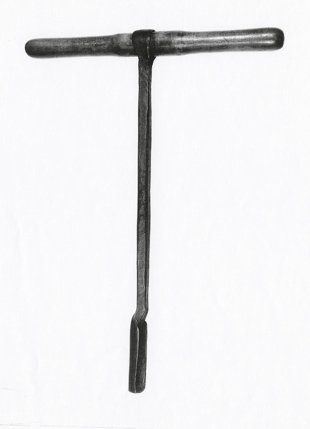
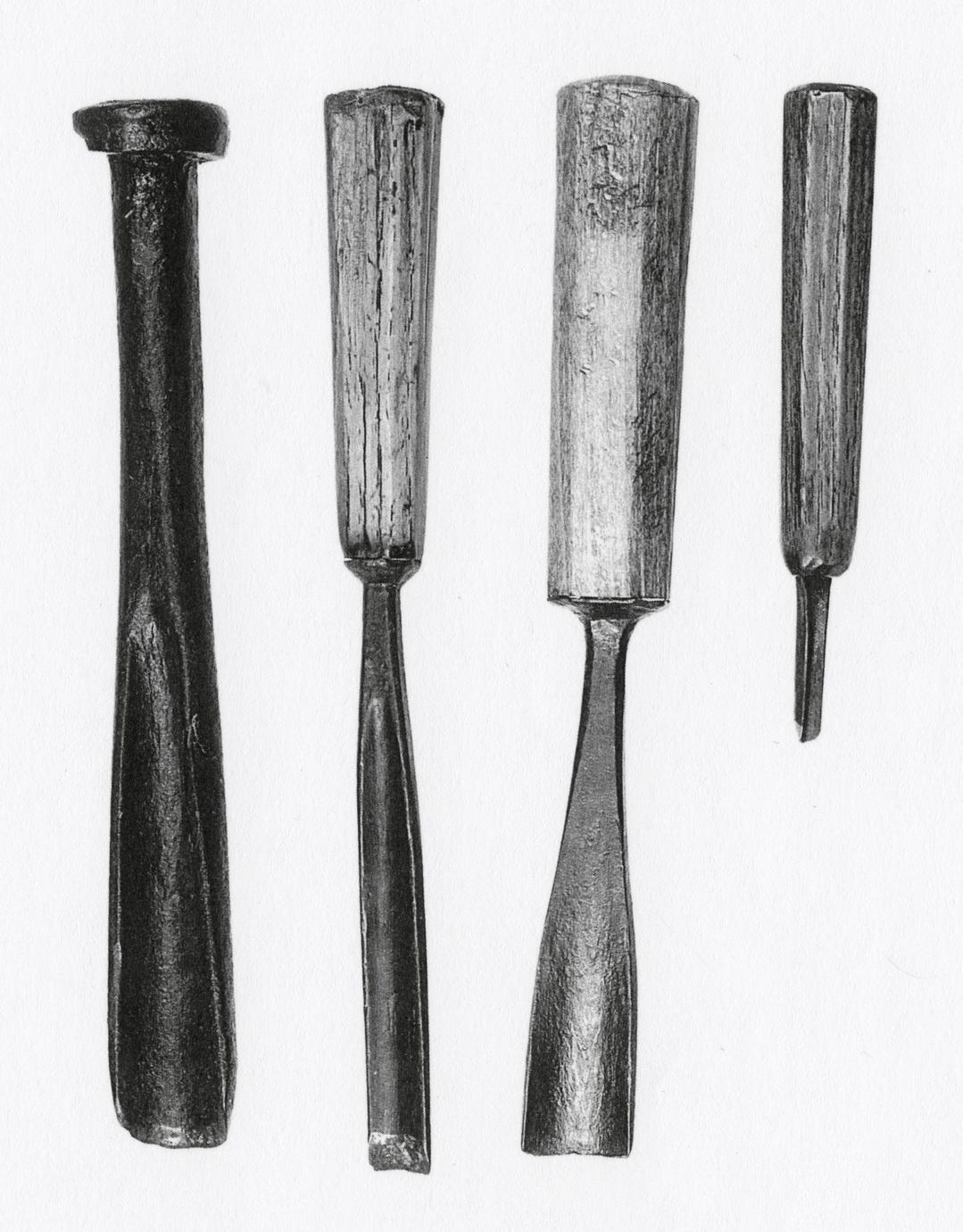
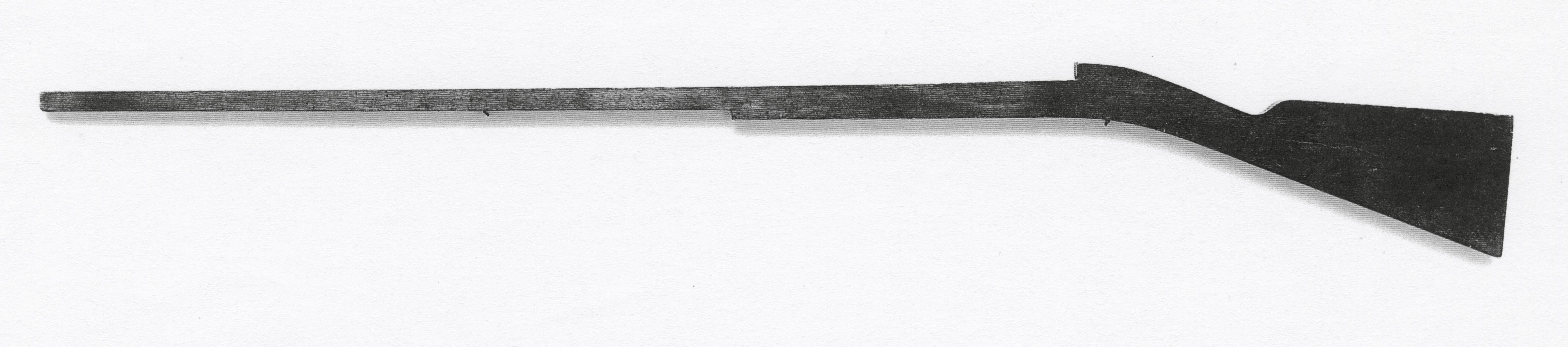
AUGERS
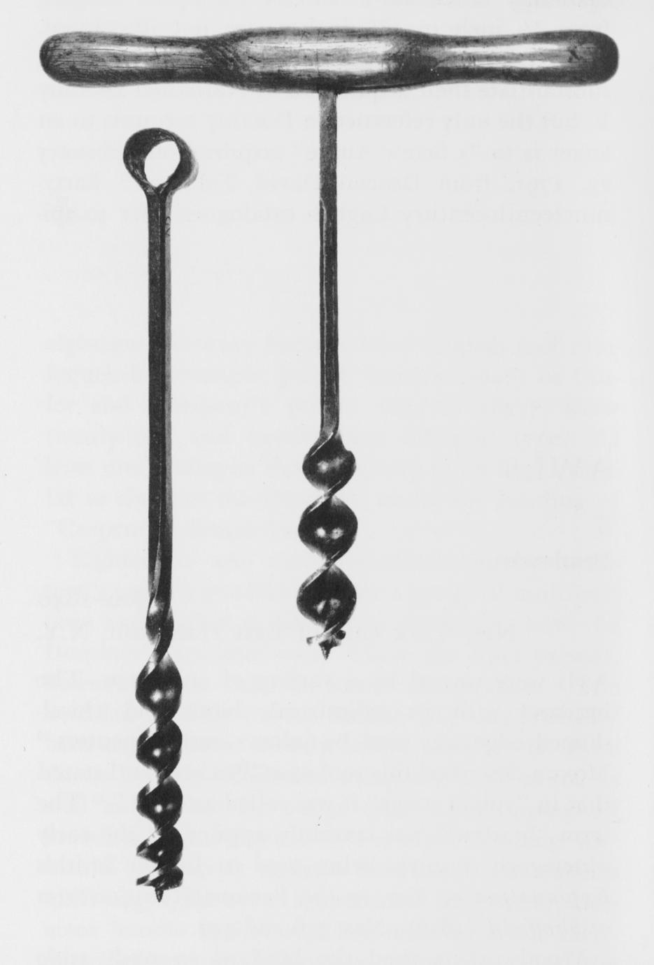
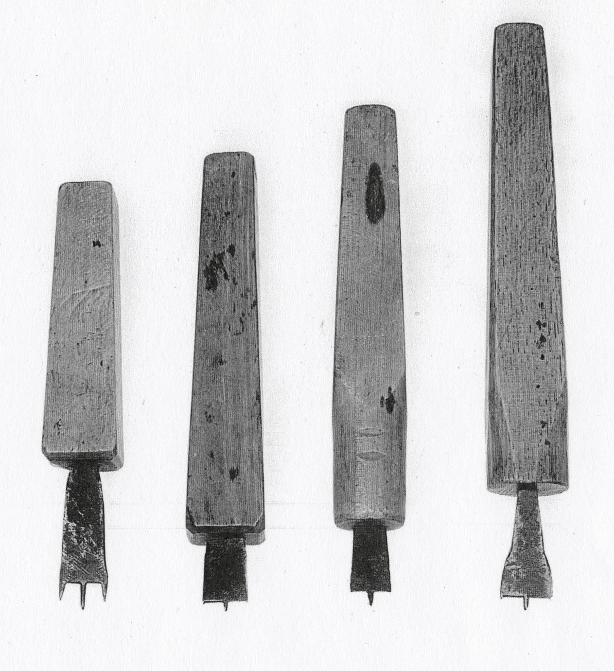
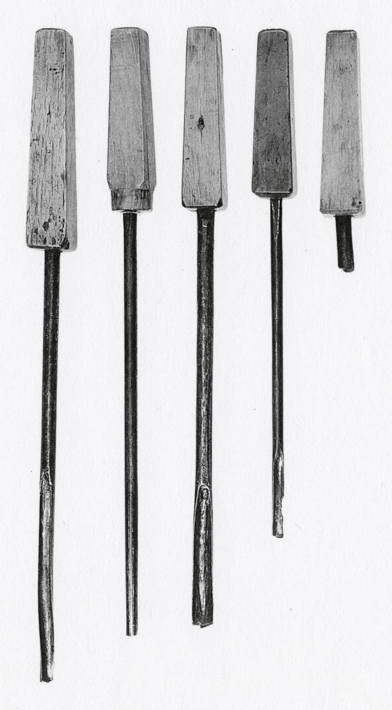
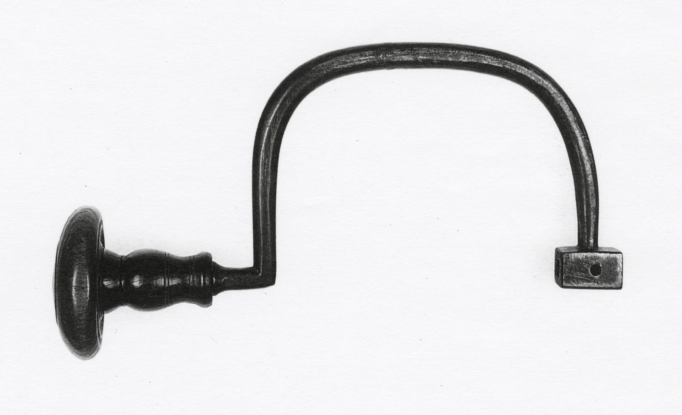
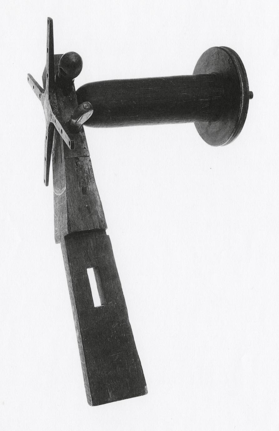
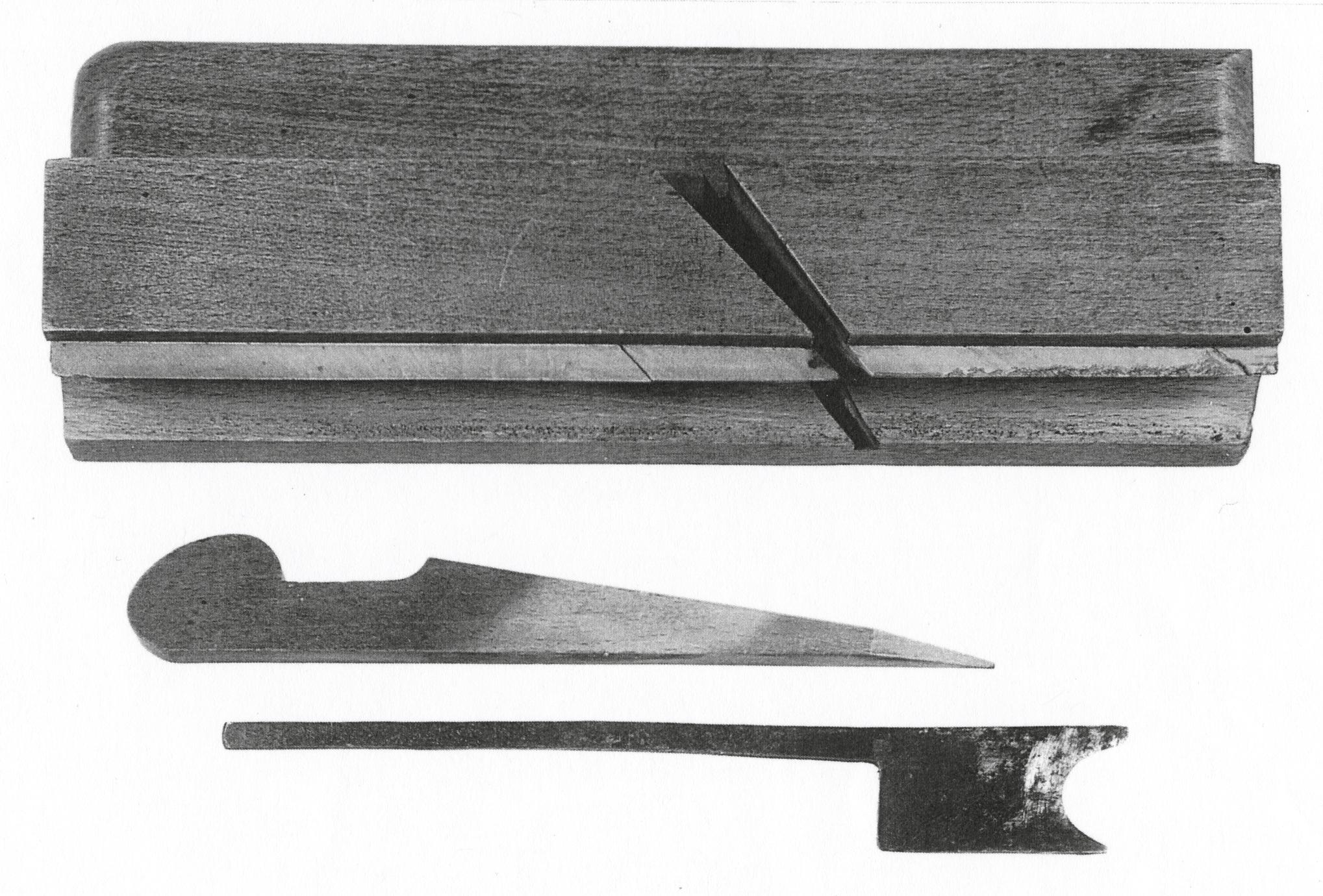
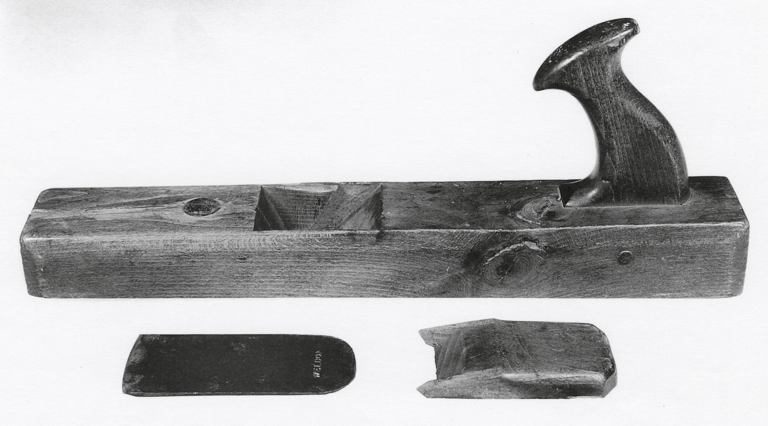
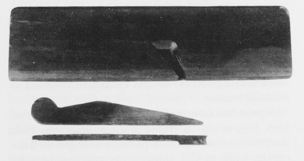
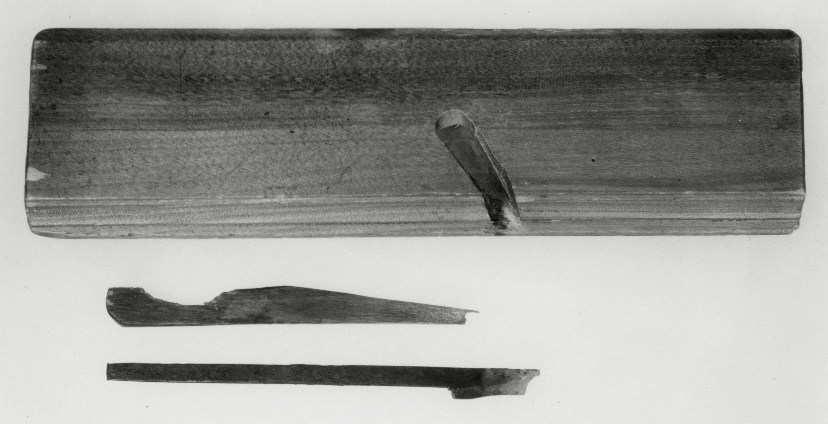
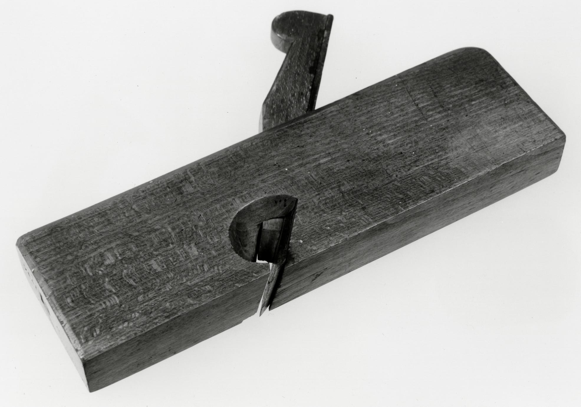
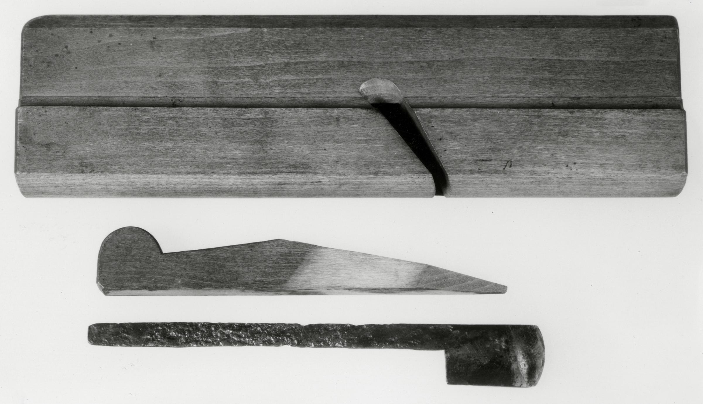
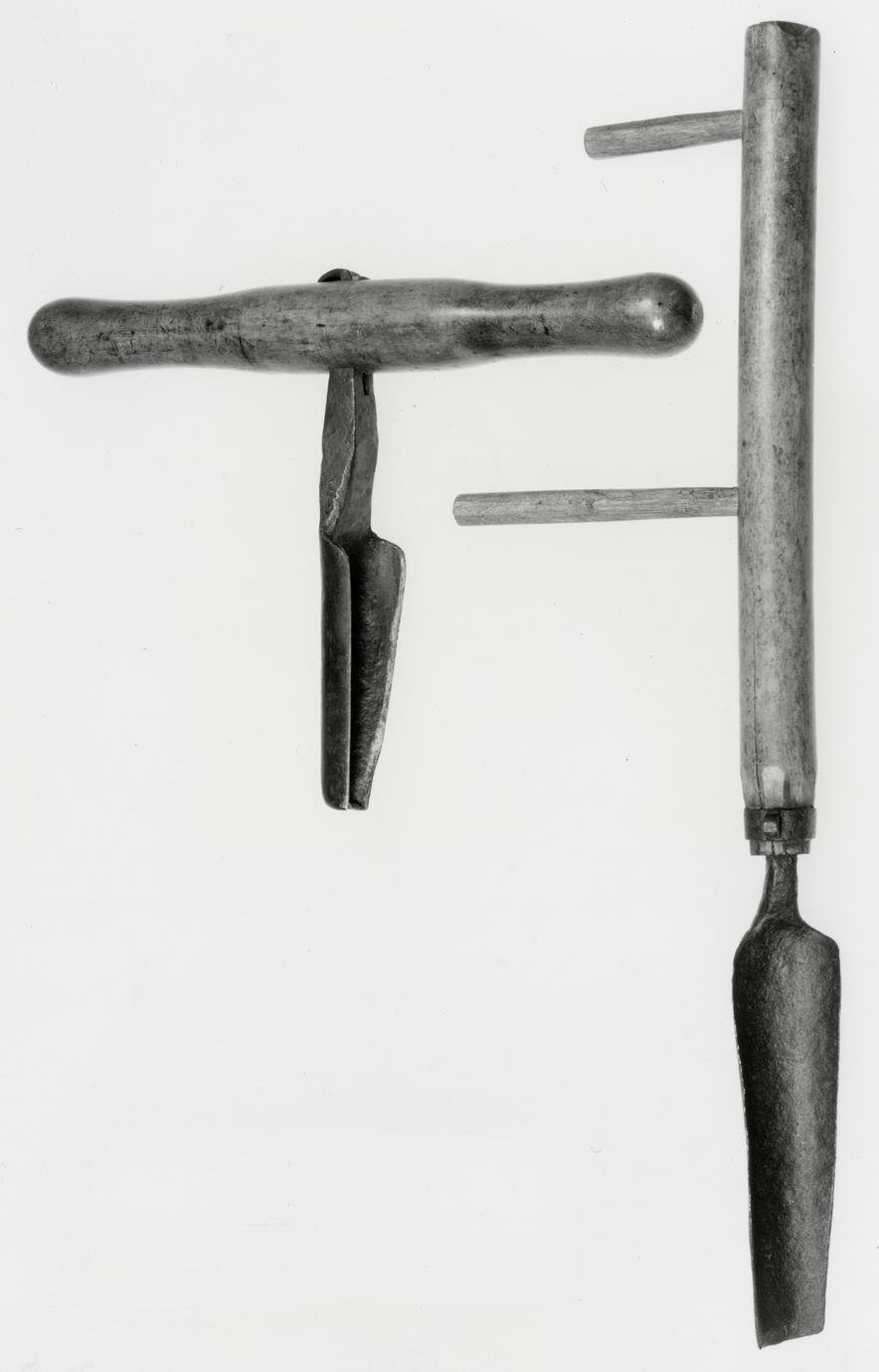
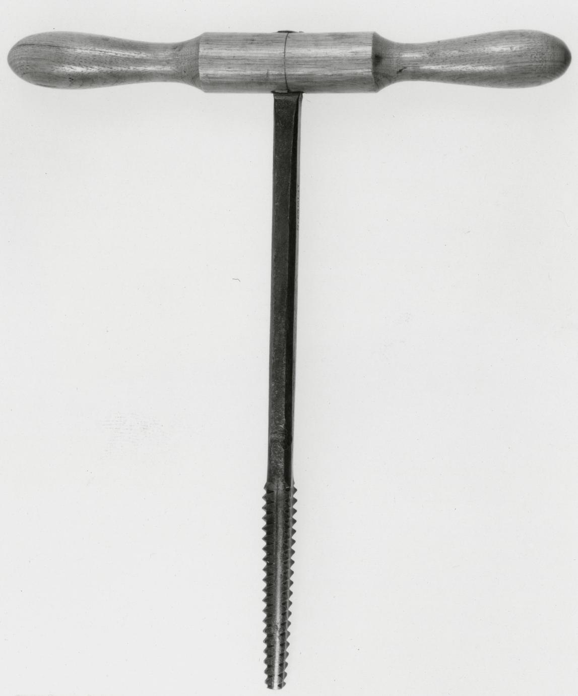
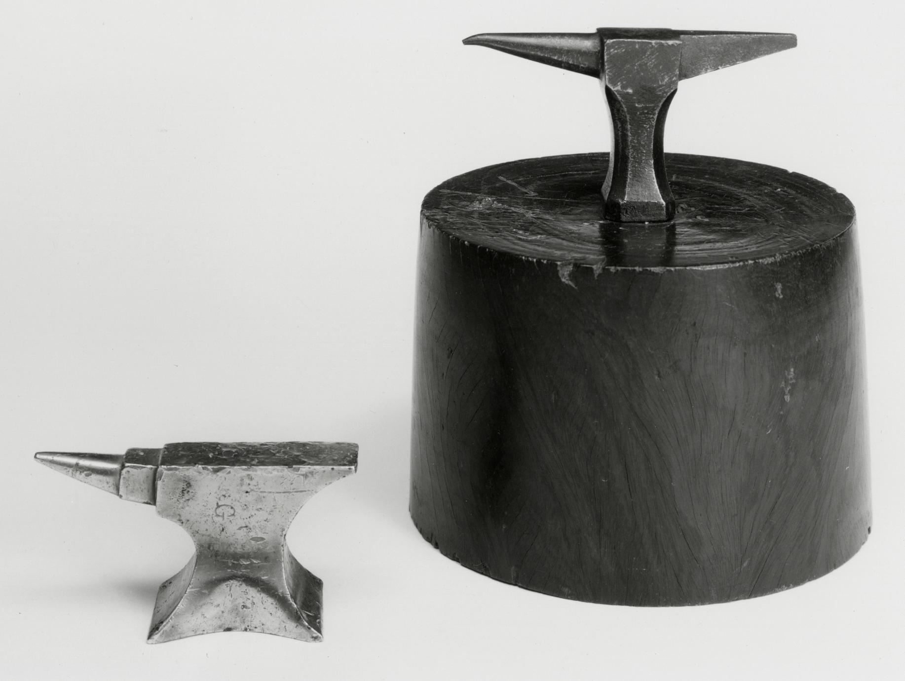
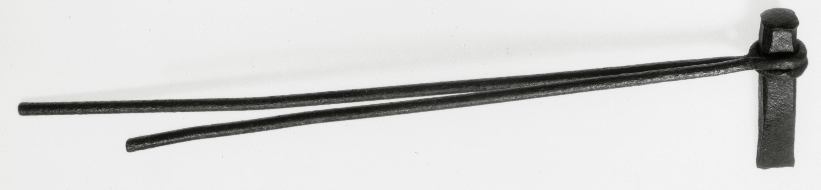
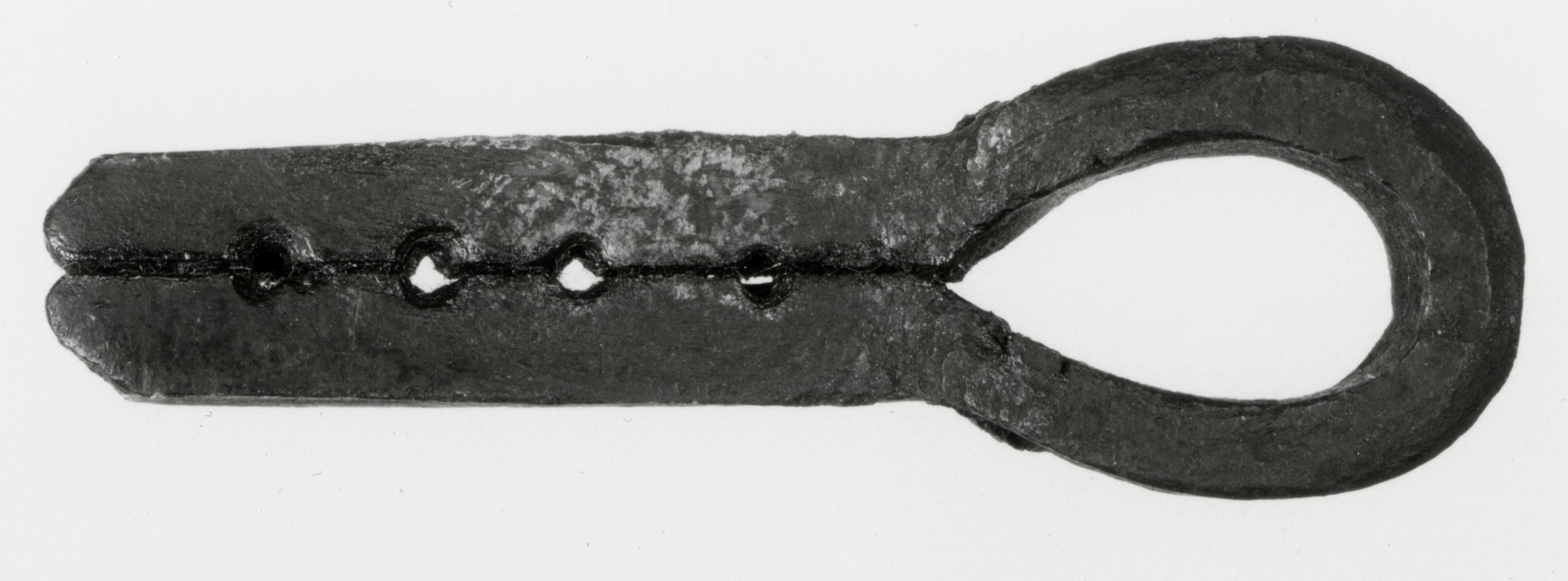
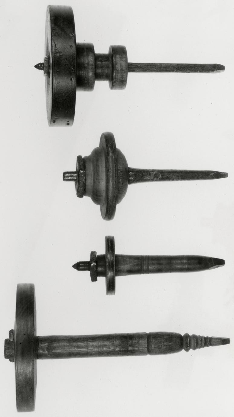
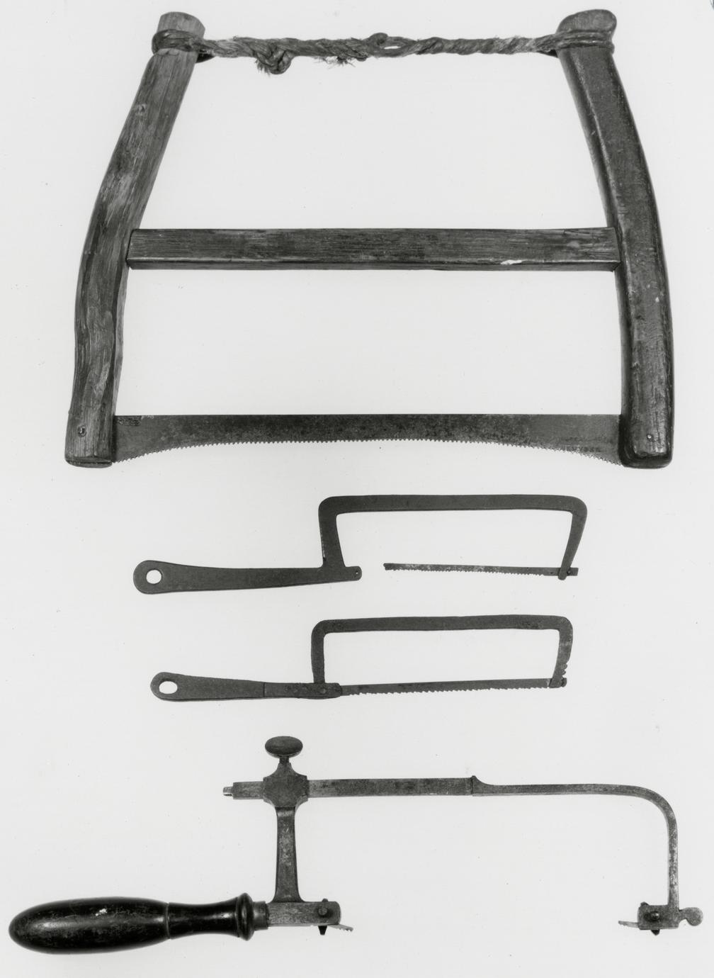
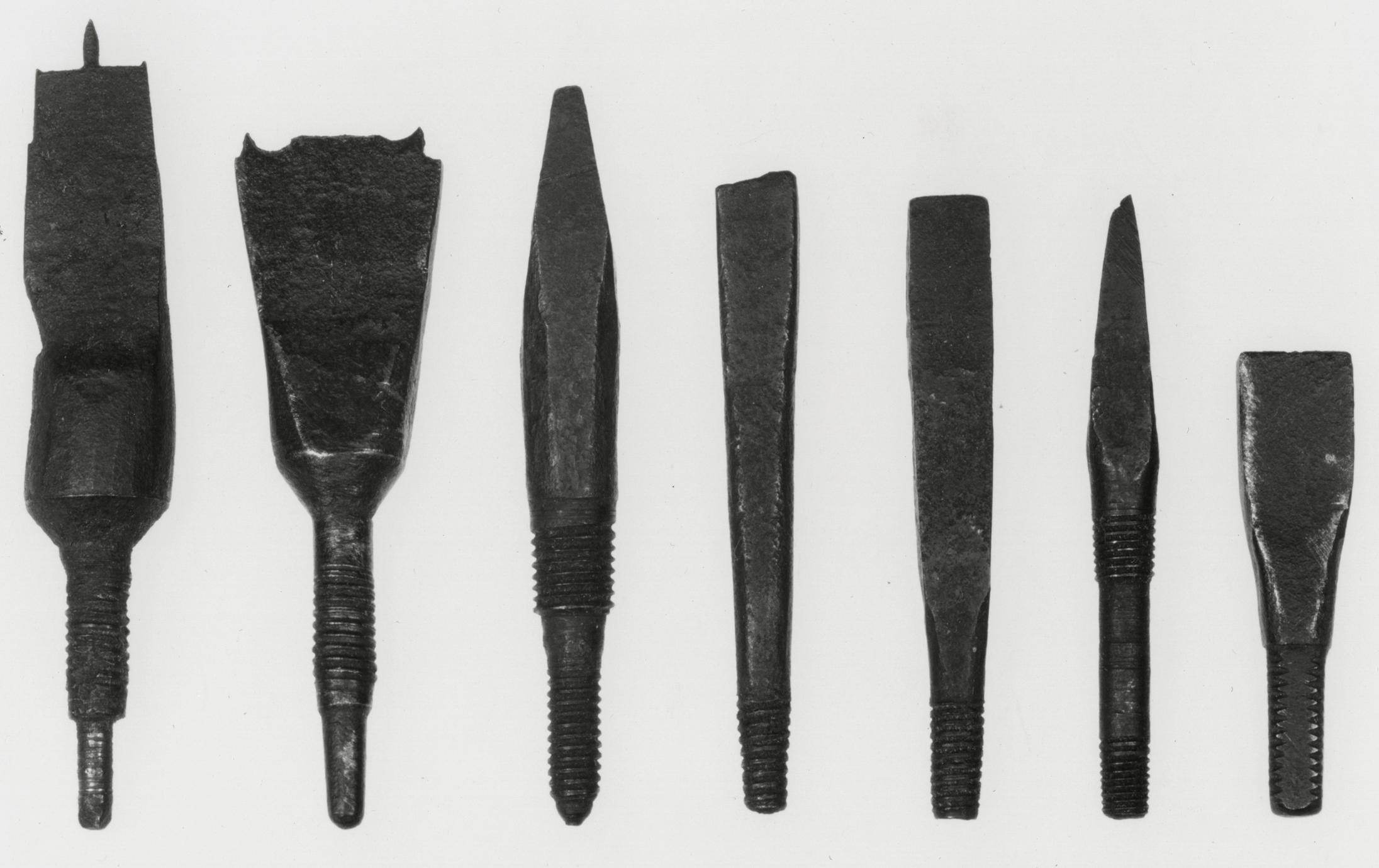
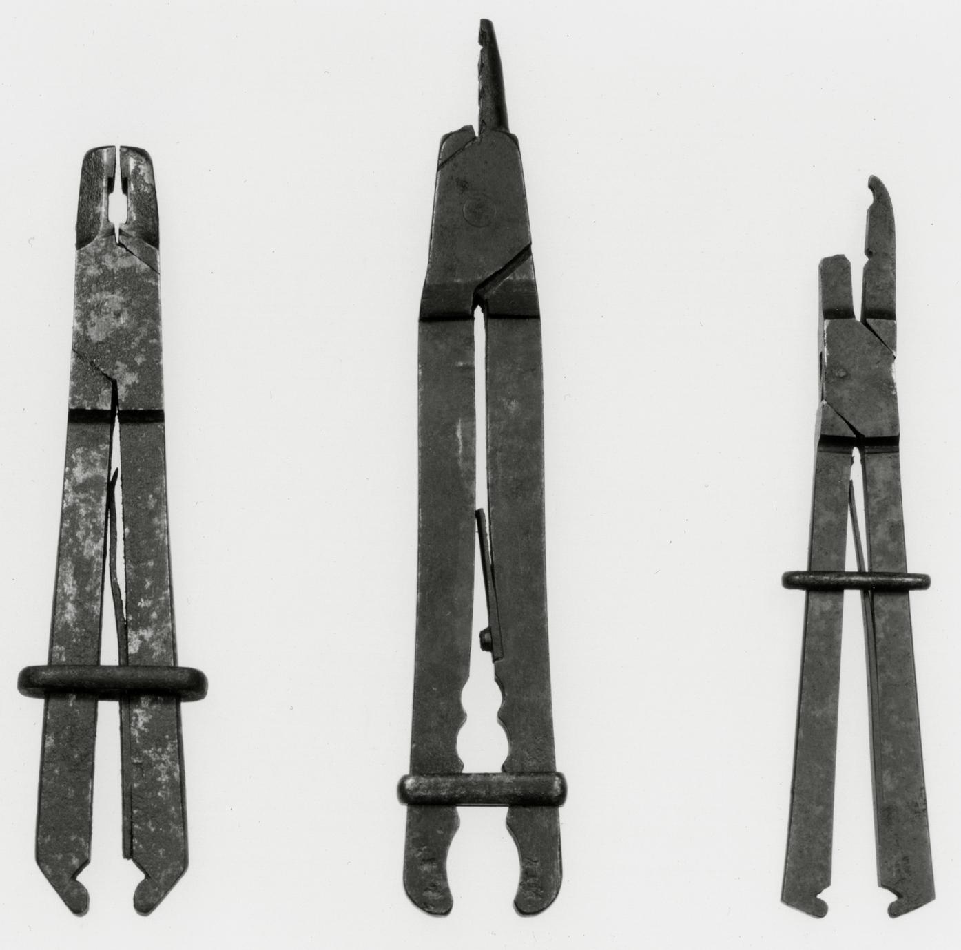
2
Nose or Downcutting Auger
1770–1830 Probably America
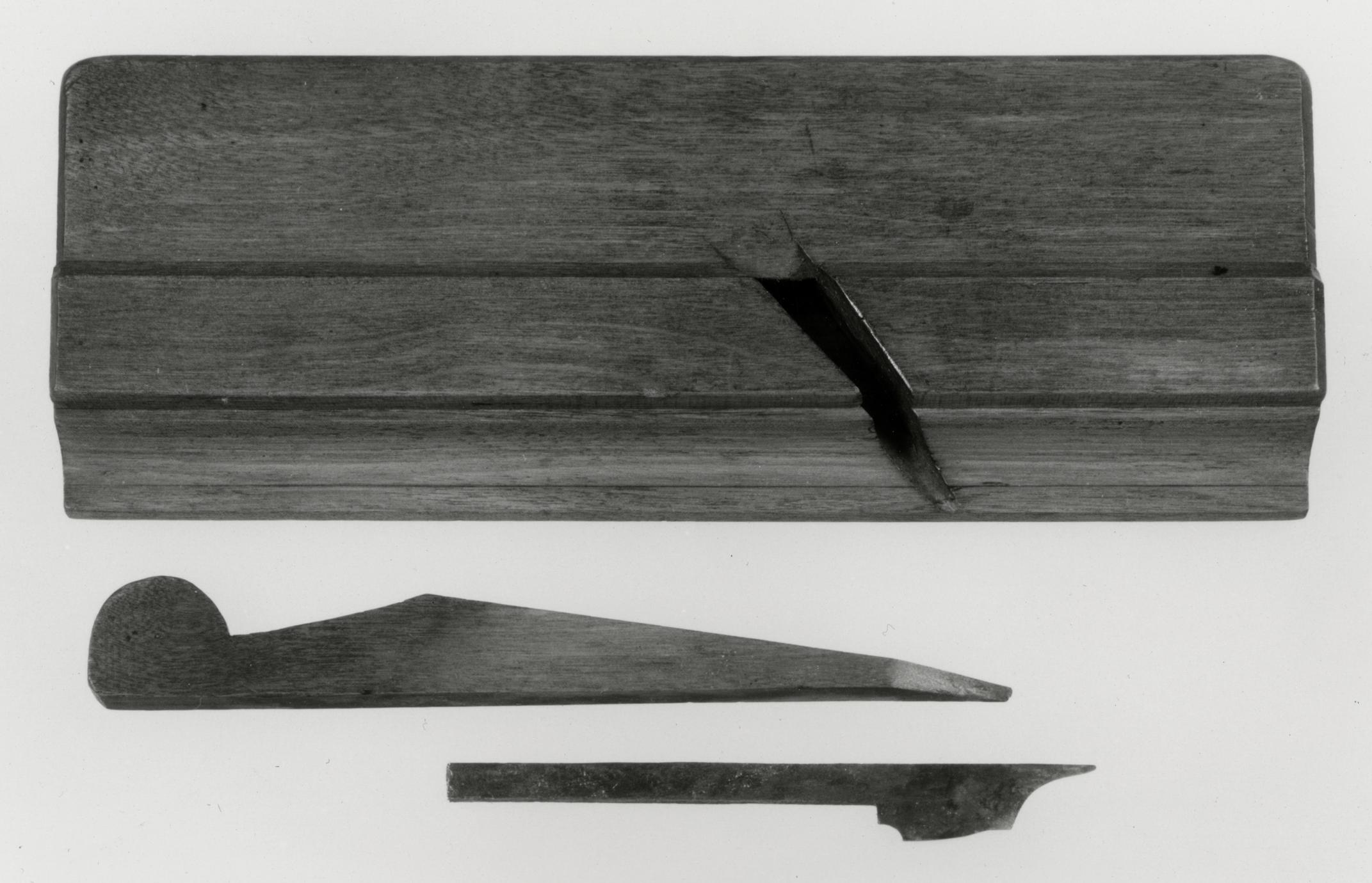
2
A notch, partially visible at the lower end of the
blade, gives the nose auger its name. Before these
augers could be used, a preparatory hole was started
by a gouge or center bit of the same diameter.10
When a hole was bored, the blade had to be withdrawn
to discard the shavings.
Great strength and pressure were needed to turn
these large augers when boring wide and deep
holes. For that reason many augers with wide
blades have a loose handle inserted through a ring,
or an eye, atop the shank, rather than a tang piercing
the handle and clinched over it as in Number
3. There has been some dispute about when the
ring and loose handle came into use. Phineas
Cooke's spiral auger of 1770 used the device, but it
also appeared in a ship's carpenter's auger found at
Novaya Zemlya in the Arctic Ocean. The auger had
been left by a Dutch expedition of 1597.11 This type
p. 45
obviously existed, therefore, before Nathaniel Dominy
IV began his career about 1760.
The initials ND were punched into the shank of
this auger, indicating ownership by Nathaniel
Dominy IV. The original handle may have been
replaced early in the nineteenth century by his son,
Nathaniel V.
Description Length, 25⅝; blade diameter,
1 11/16; handle width, 18½. Iron eye, shank, and cutting
blade; soft-maple handle. Probably purchased
by Nathaniel Dominy IV or Nathaniel Dominy V.
Museum accession: 57.26.103.
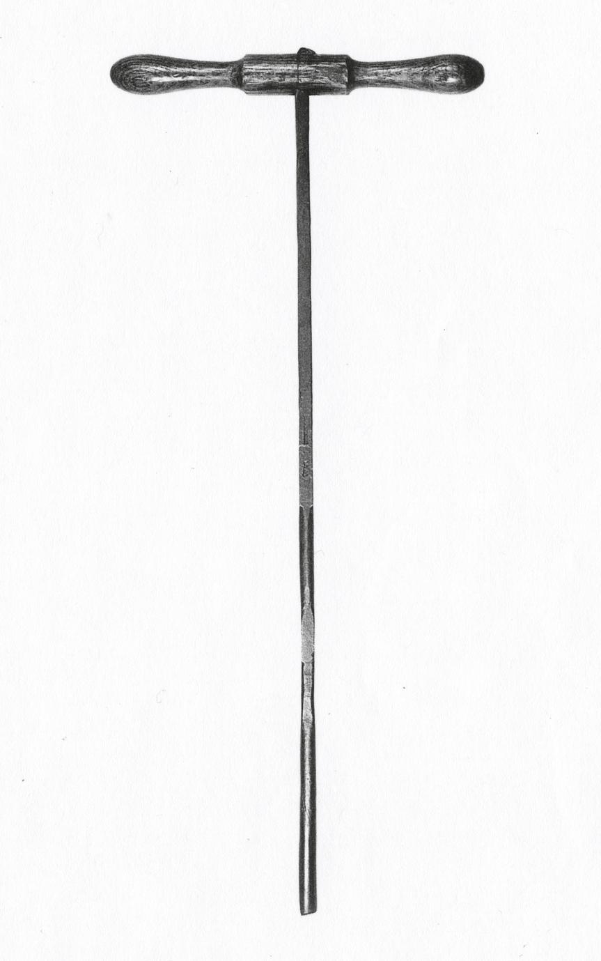
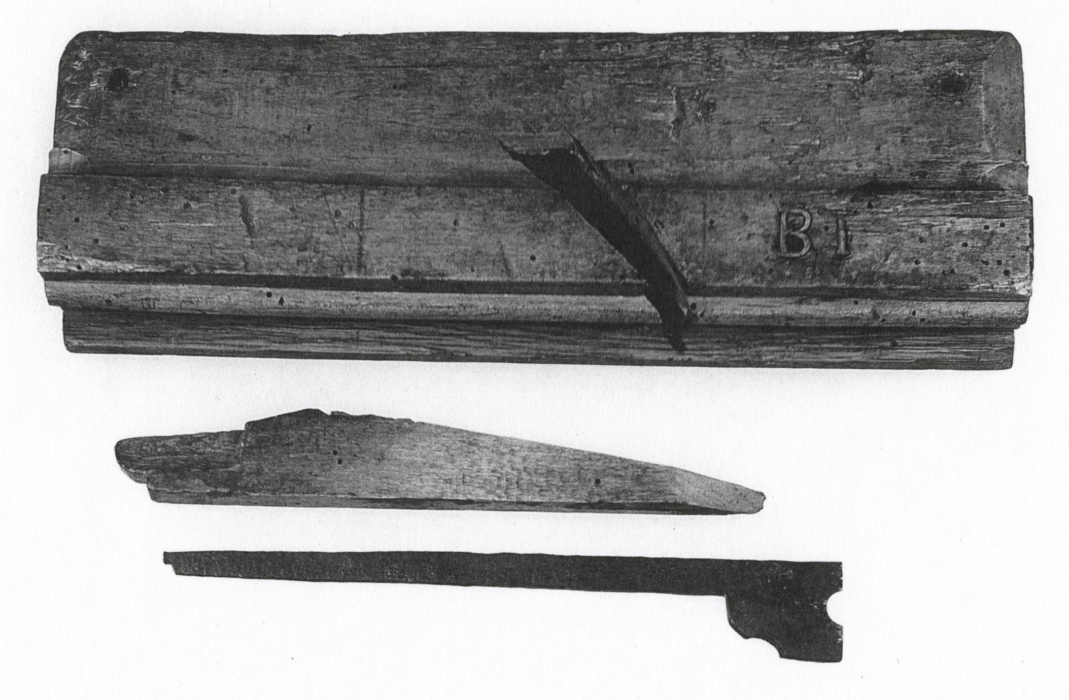
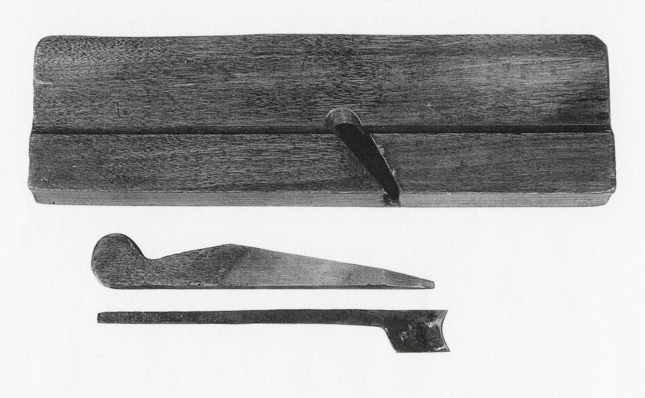
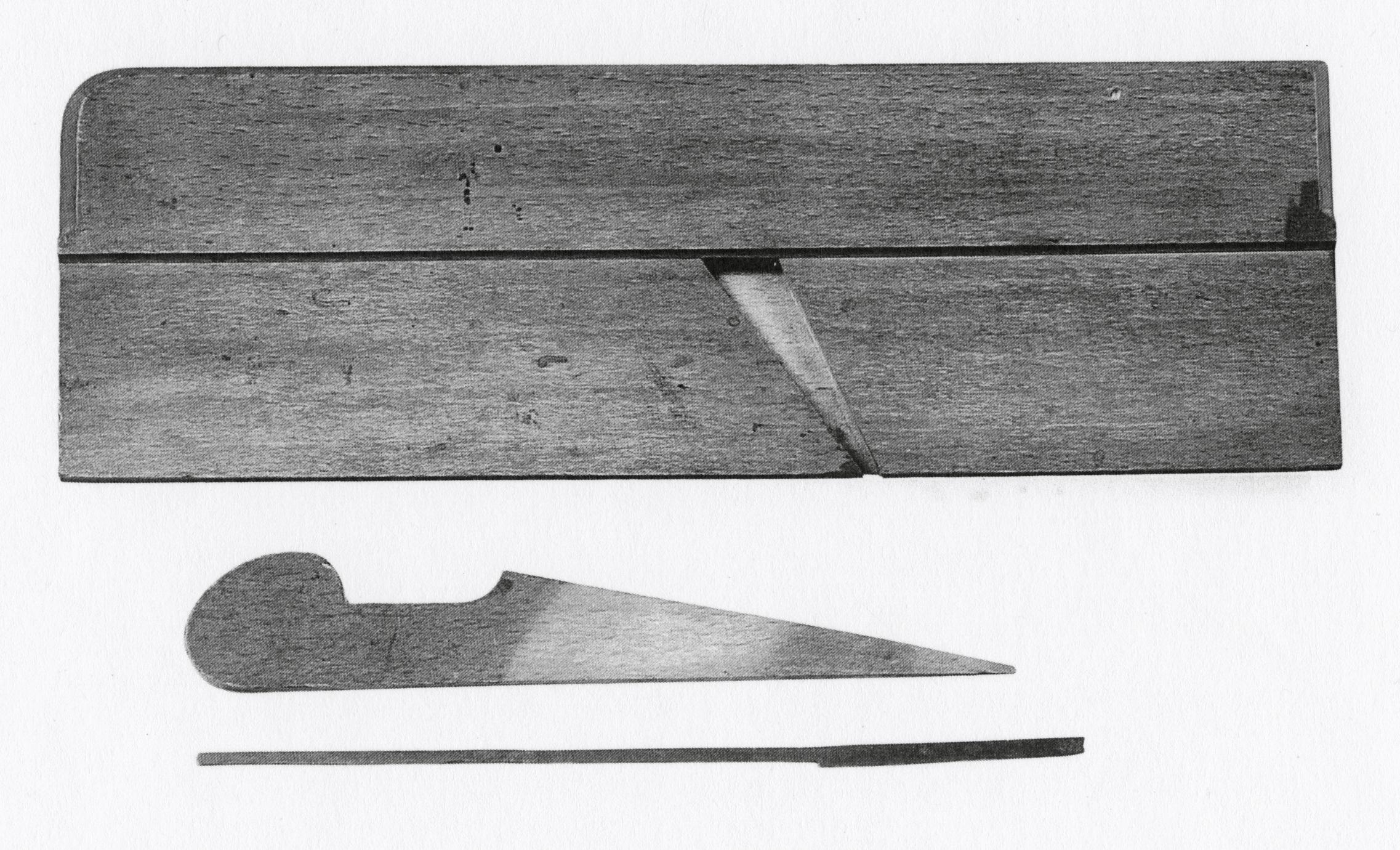
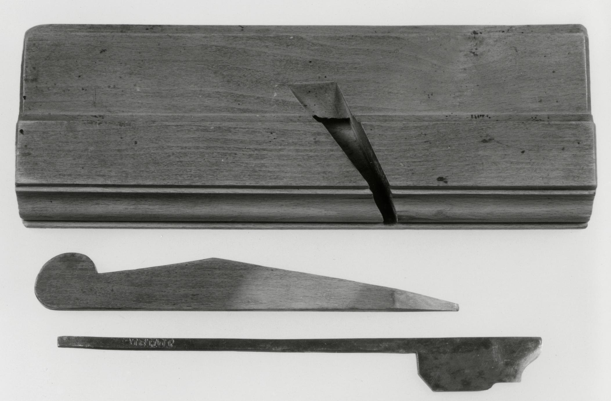
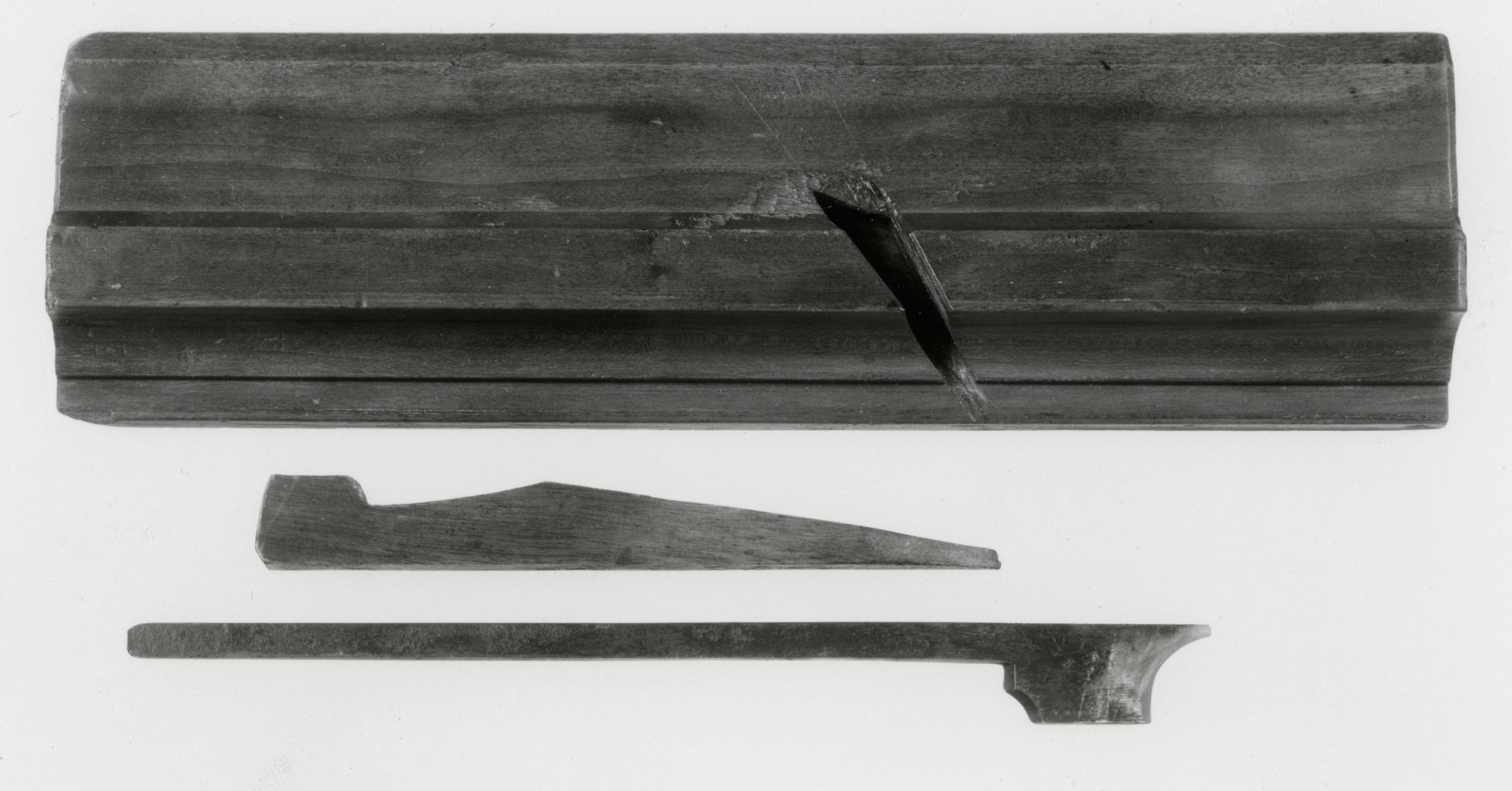
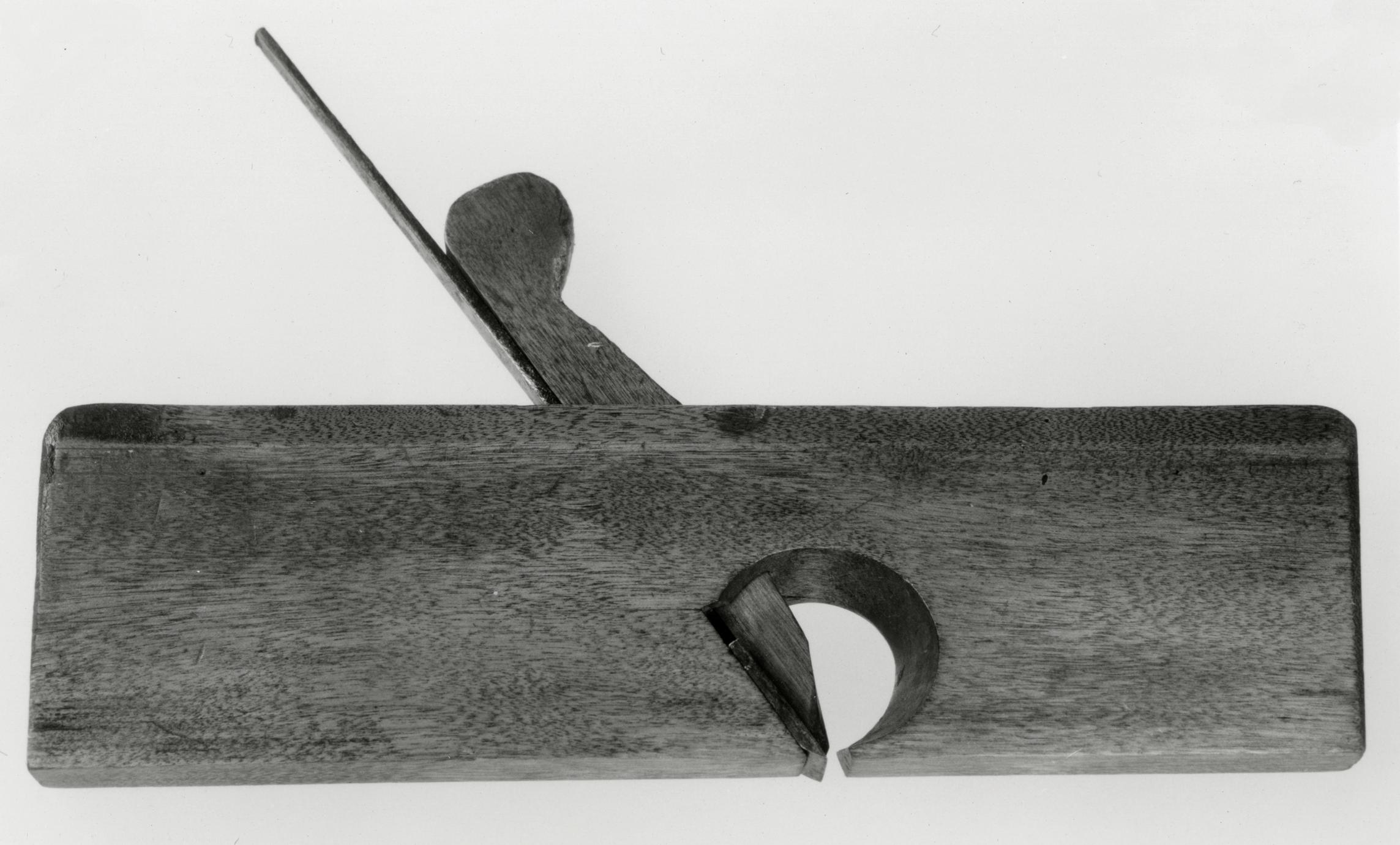
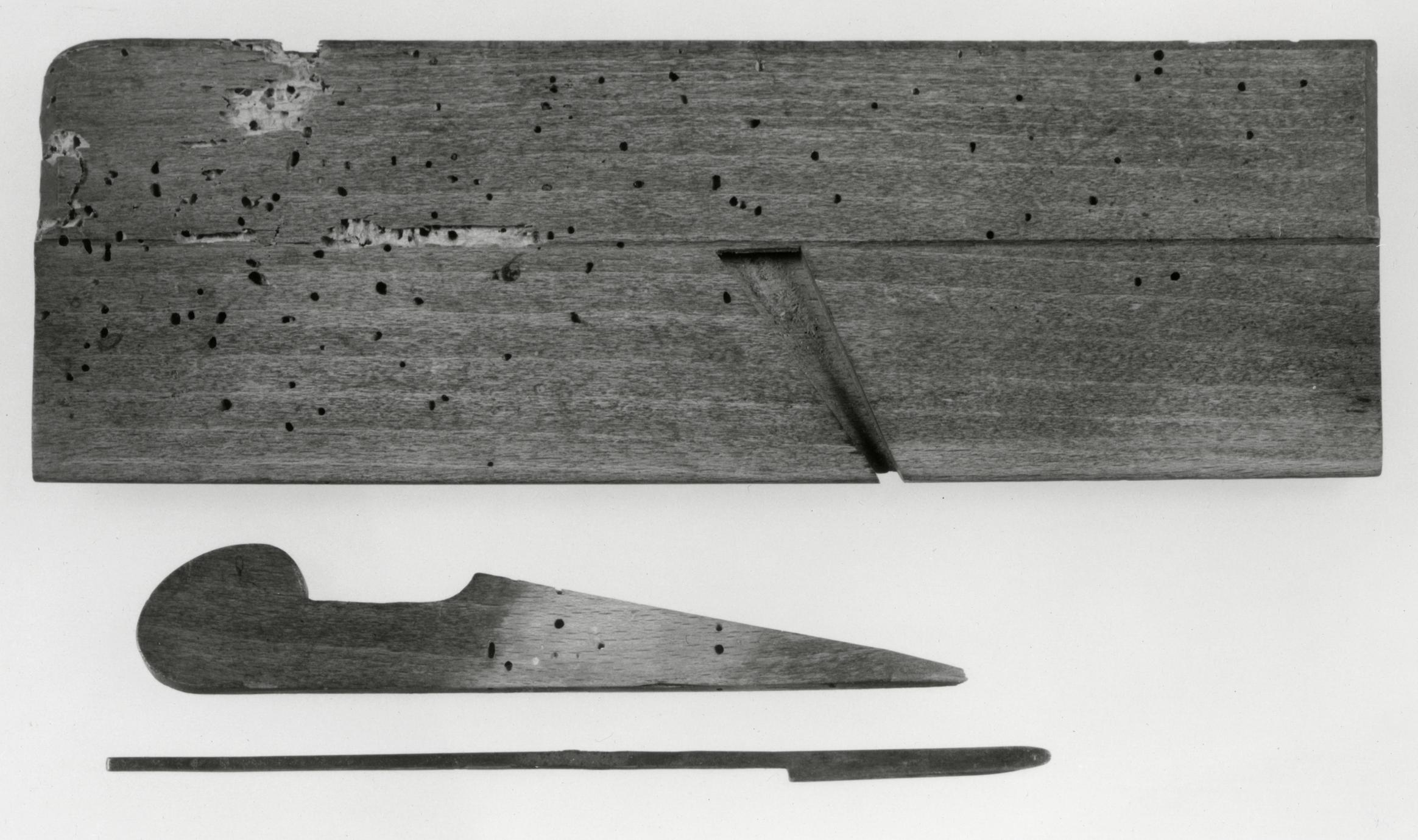
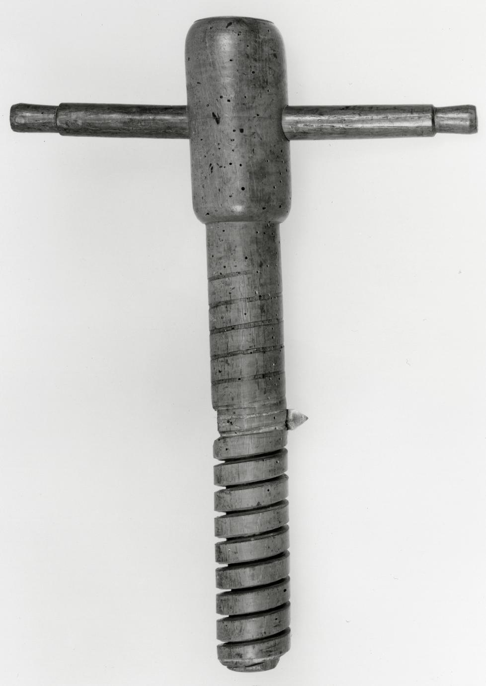
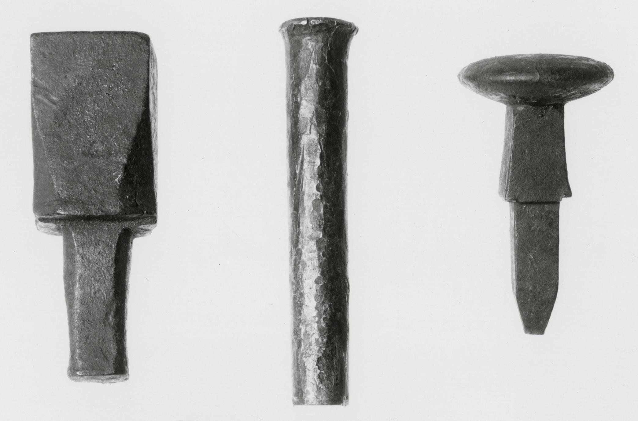
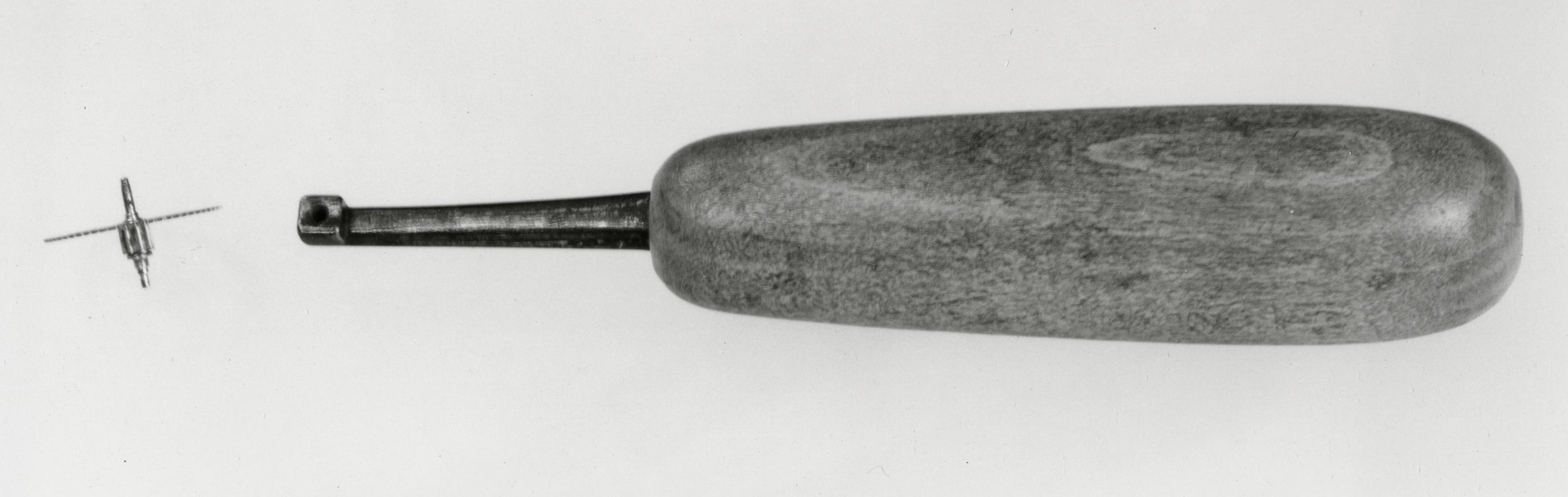
3
Nose or Downcutting Auger
1775–1800 Probably America
3
The auger was an important tool for carpenters and
wheelwrights. It enabled them to bore holes of a
width and depth impossible to achieve by using
lighter wood-boring tools such as the brace and bit
or gimlet (Nos. 20, 39).12
Cutler and Company, of Sheffield, England, describes
this tool as a "Shell" auger, and their catalogue,
published about 1833 to 1837, advertised
eleven diameters for the tool that ranged from ½
inch to 2 inches. Other contemporary sources
merely refer to this slit-nosed form as an "auger," as
a "carpenter's" auger, or, with a longer pod, as a
"ship carpenter's" auger.13 The notched spoon
blade, with one projection sharpened to form a
"nose" in profile and the other projection bent
upward to clear and hold the shavings from the
hole, is not seen in eighteenth-century illustrations.14
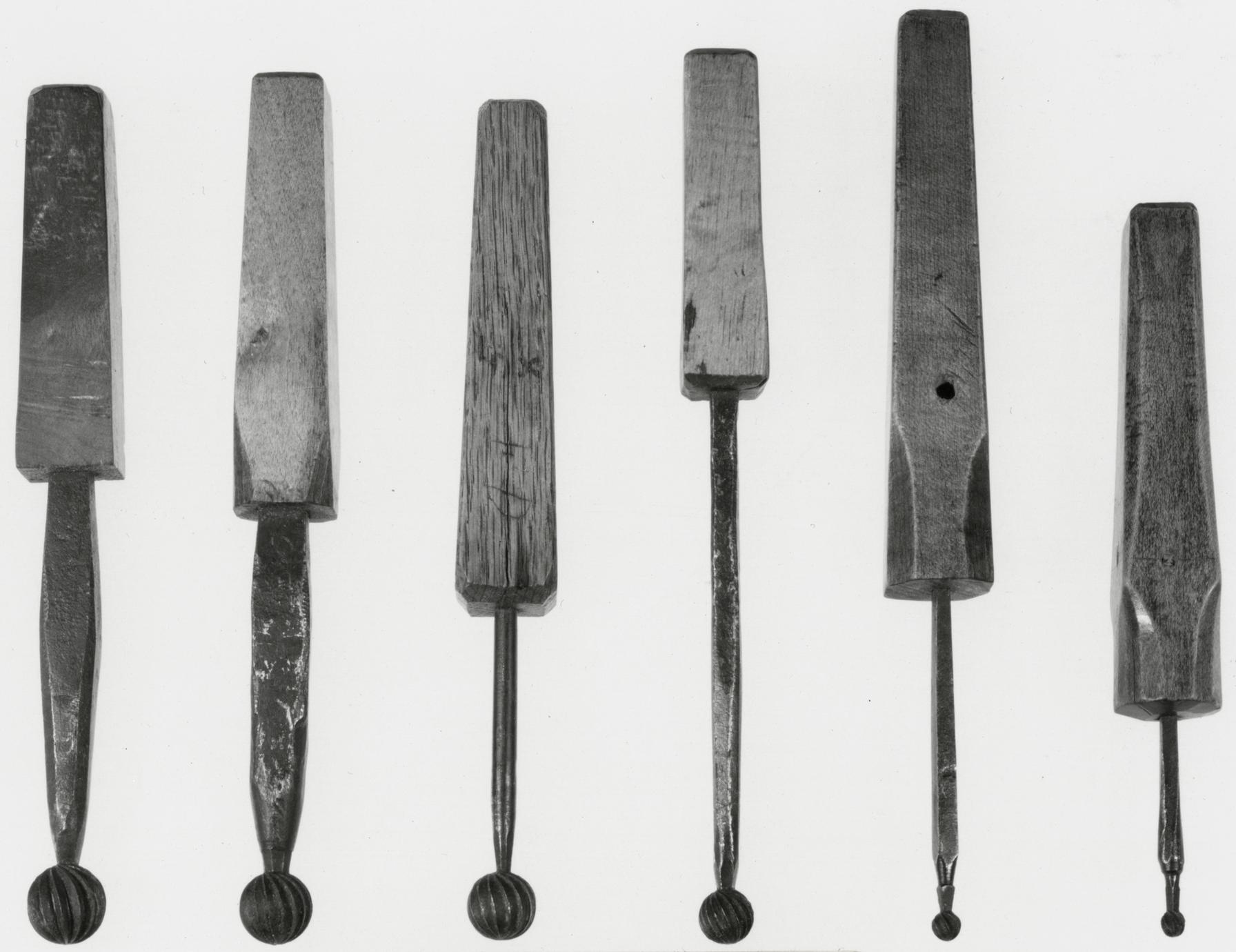
In addition to the examples illustrated (Nos. 2,
3, 4), three other nose augers used by the Dominy
craftsmen have survived. These range in length
from 14⅜ to 27¼ inches and have cutting edges
with diameters of 1⅛, 1¼, and 1 7/16 inches. One of
these (57.26.110) has a shank stamped S. HORTON
inside a serrated rectangle.
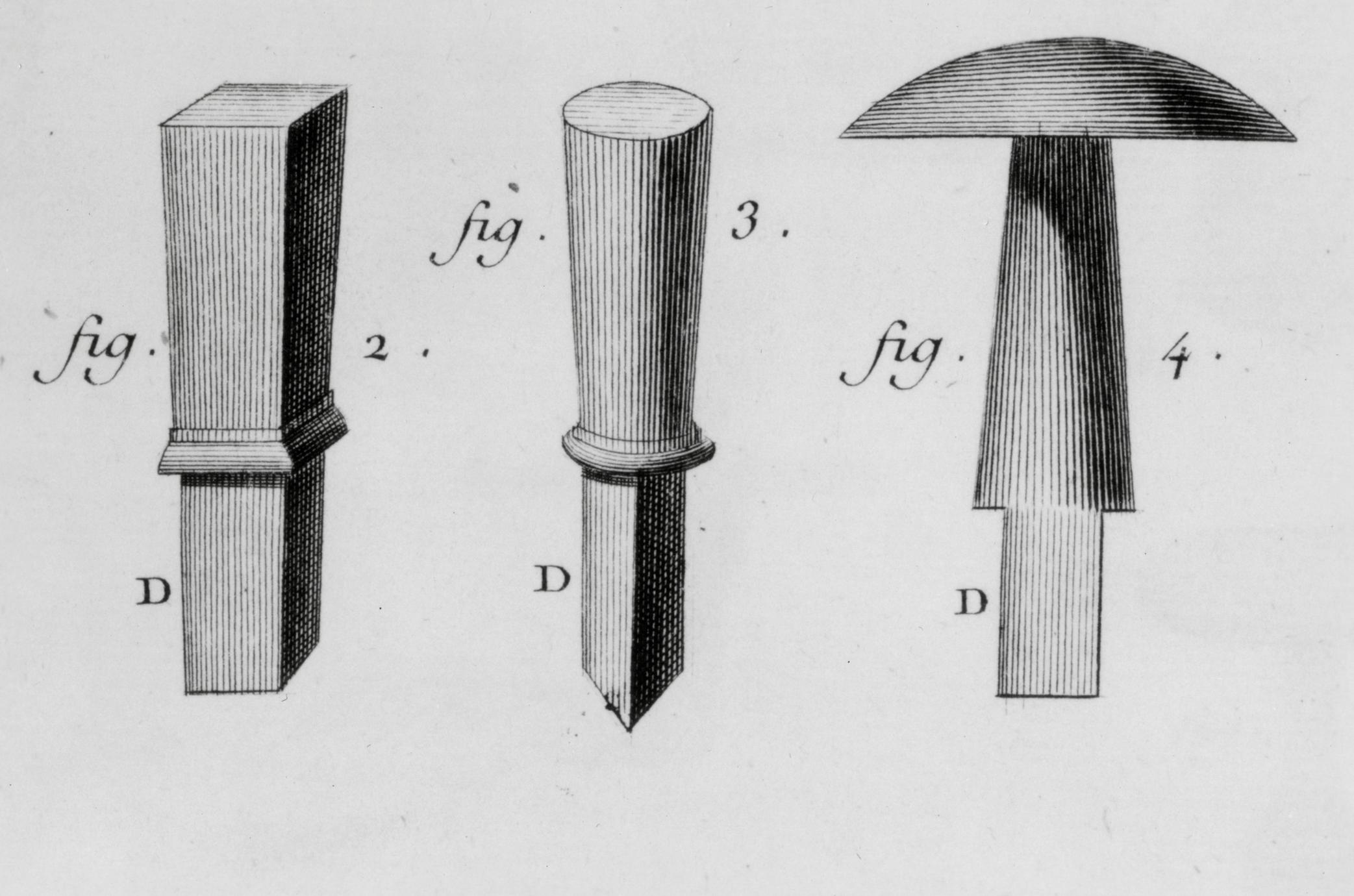
The handles used on each of the three nose augers
illustrated are different. In this example the
auger's tang pierces a narrow cylindrical section
flanked by circular, tapered handgrips similar to
the handle shown on a screw tap illustrated by
André Jacob Roubo (see p. 139). This handle also
bears some resemblance to one used by Ezra
L'Hommedieu for his patented screw auger of 1809.
That handle, however, had a more pronounced concave-shaped
handgrip with much rounder ends and
a shorter, thicker central cylinder.15 The early type
of handle, plus the long three-piece iron shank,
helps to date the tool in the last quarter of the
eighteenth century.
Description Length, 22⅜; blade diameter, ½;
handle width, 10. Iron blade, shank, and tang; hickory
handle. Purchased and used by Nathaniel Dominy
IV. Museum accession: 57.26.105.
p. 46
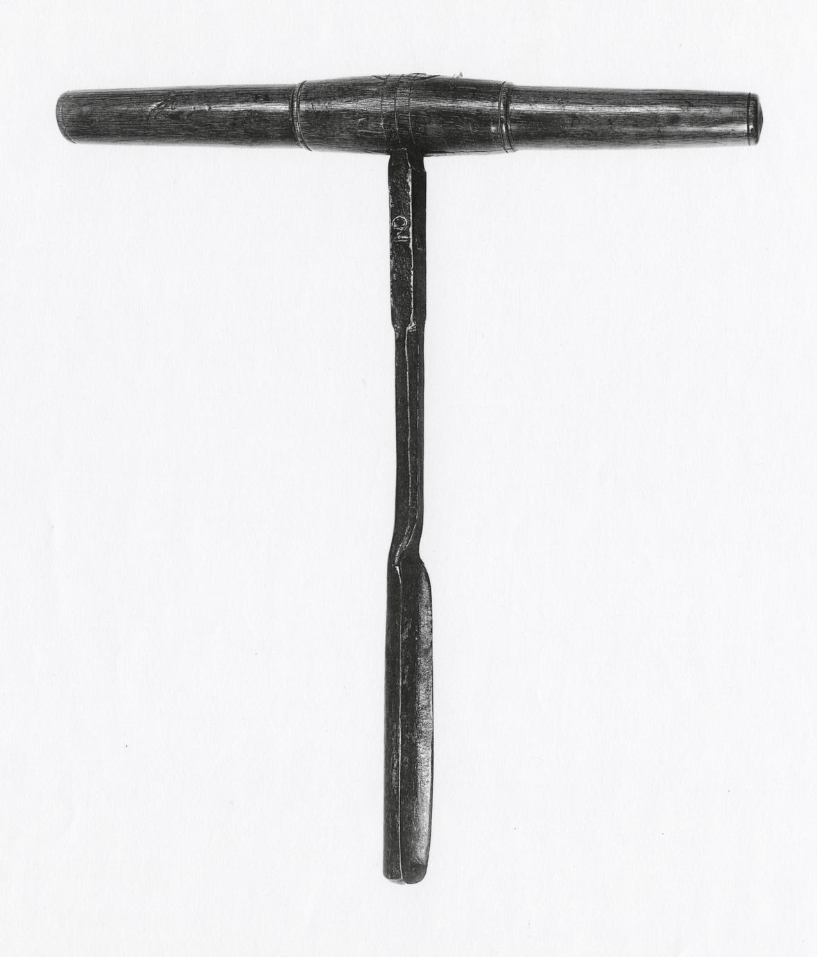
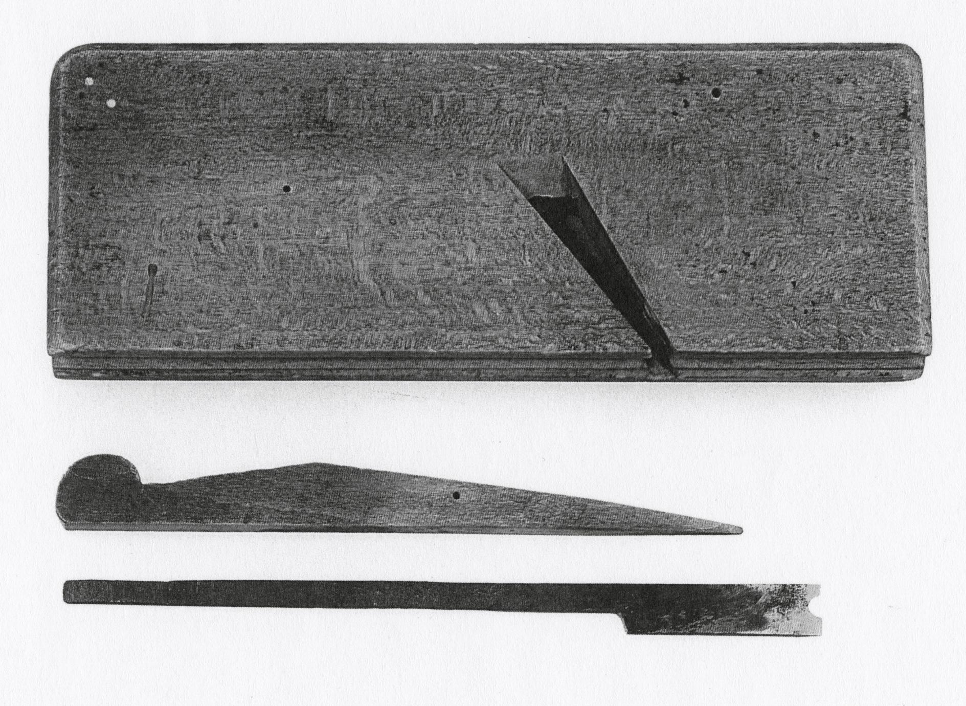
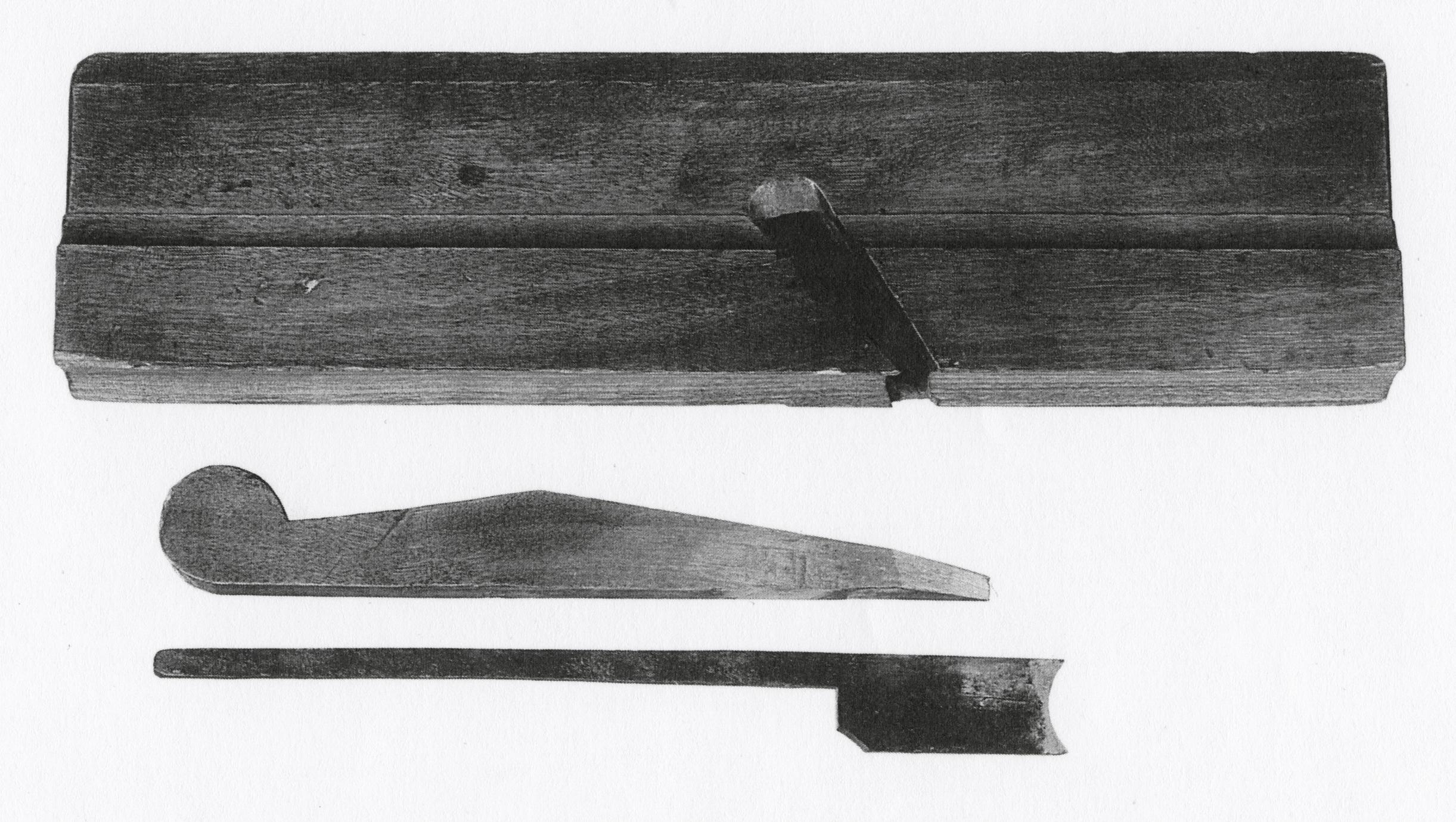
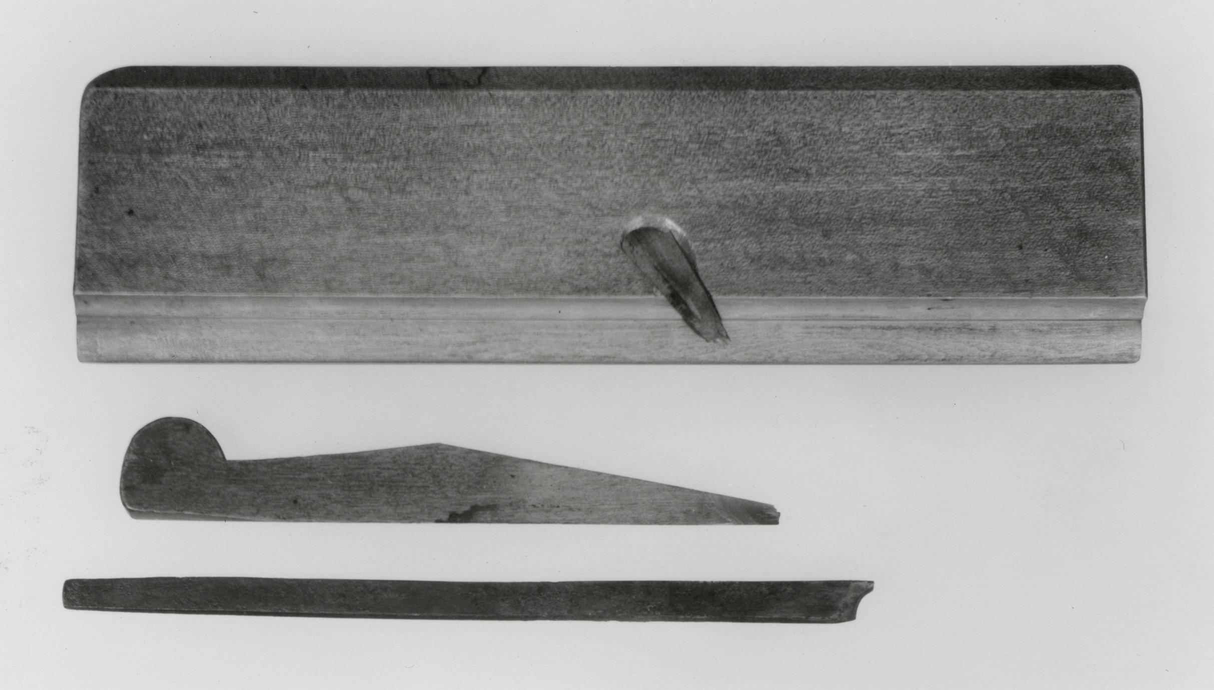
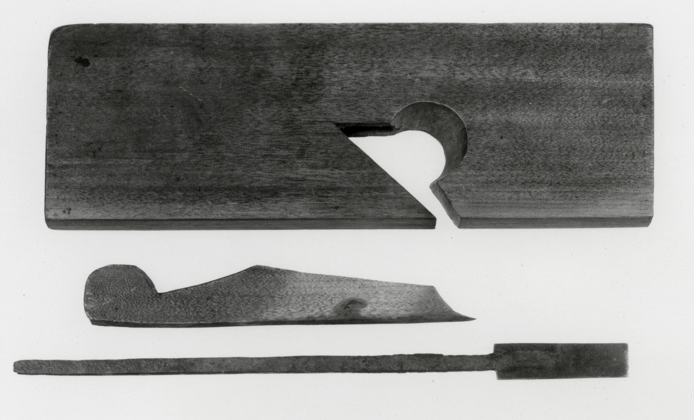
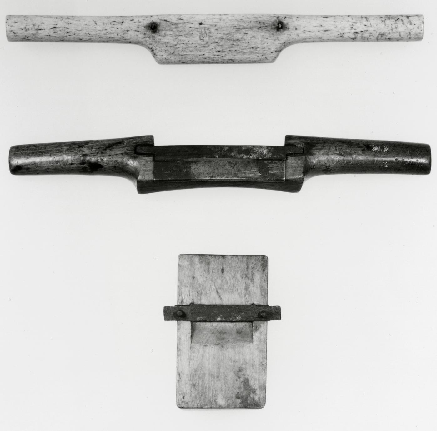
4
Nose or Downcutting Auger
1800–1830 England and America
4
It took considerable skill to use an auger properly.
Nowhere is that made so evident as in a description
of the tool furnished by James Smith about 1815 or
1816:
The largest of the boring tools for wood, is the
auger. The oldest construction of the auger, which
is yet in common use, in various parts of the country,
cannot be wrought till a small excavation has
been made, which is mostly done with a gouge, at
the place where the hole is to be; and till the auger
arrives at a considerable depth, the motion of it is
very unsteady. This old auger is shaped like a gimblet,
except at the point, which is like that of a nosebit.
Everyone who makes use of an auger in the usual
way by hand, knows by experience that he never
can so completely exert his strength in this operation,
as when he bores down perpendicularly, with
his body leaning over his work; and it is very evident
by every degree of the auger's elevation from
this situation, his power is of less effect, consequently
his labor is increased, and his work so much
retarded, that in the former position he can bore
four holes for one in the latter. In the hand boring,
also, the unsteady and irregular motion of the auger,
(particularly when the common old-shaped
one is used), at its first entrance into the wood,
occasions the holes to be bored very crooked, often
larger without than within, and very wide of the
direction aimed at, especially if the wood proves
hard and knotty, and the holes are deep.16
Smith's description gives evidence of another tool
for preparing the starting hole—the gouge—and
also shows that the nose auger was still commonly
used in the nineteenth century. It was not until the
last quarter of that century that the spiral auger
completely superseded the older form.17
This nose auger may be earlier than the dates
indicated. The conjoined initials ND are stamped
twice on the handle and are also chiseled into the
shank just below the handle. These initials are
Gothic, however, and the handle is of a later,
lathe-turned type. These clues probably indicate
purchase of the auger by Nathaniel Dominy V. The
initials WR over E are also stamped on the shank
and are of a type used by Birmingham toolmakers
to mark their products.
Description Length, 20; blade diameter, 17/16;
handle width, 17⅛. Steel blade, shank (stamped
ND and WR over E), and tang; American white-oak
handle stamped twice ND. Probably purchased by
Nathaniel Dominy V. Museum accession: 57.26.106.
p. 47
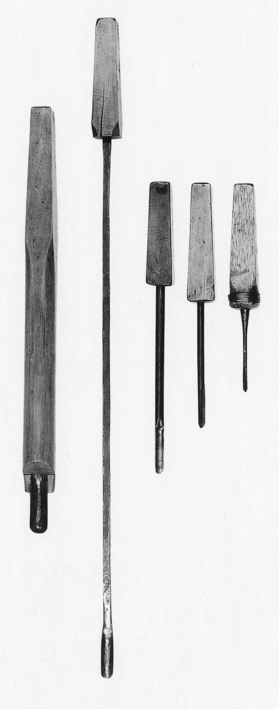
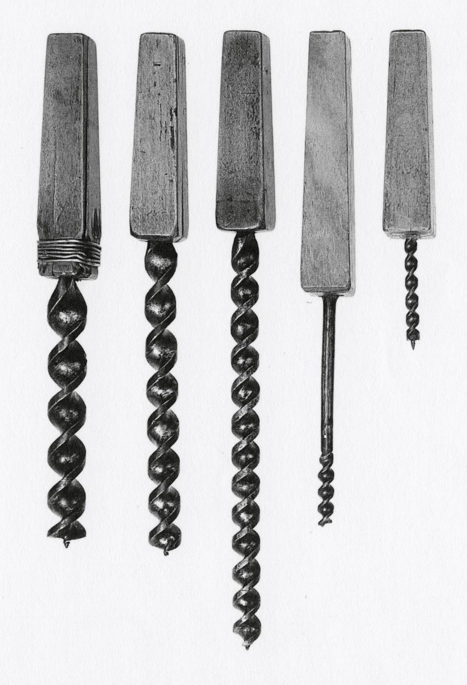
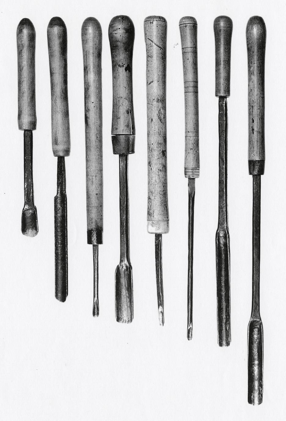
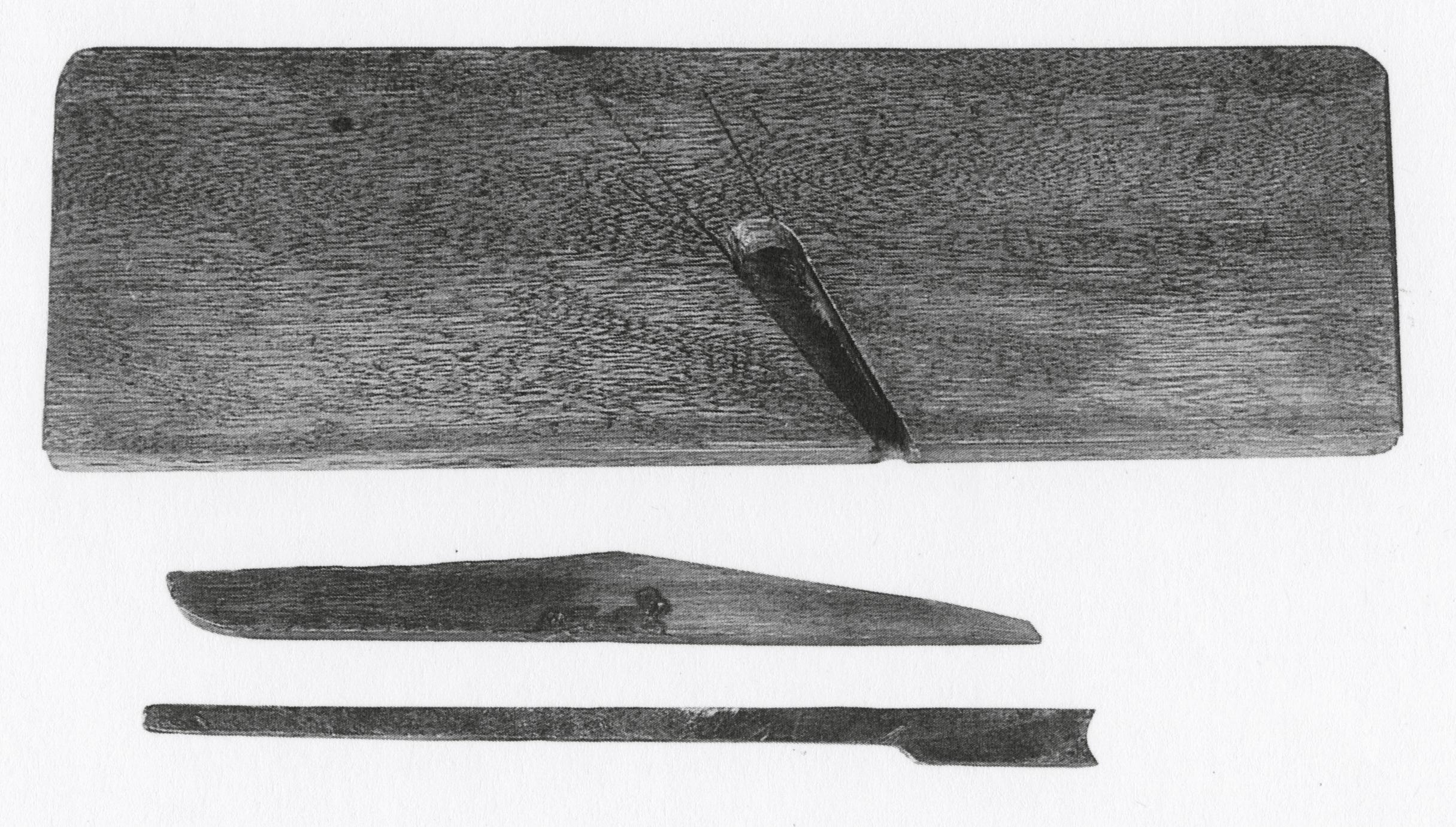
5
Spiral Augers
1810–1830 Probably America
5 A, B
The double-podded center-screw auger with twisted
shank, patented by Ezra L'Hommedieu in 1809, was
not the first spiral auger. It was, however, so great
an improvement over earlier types that its special
position in the history of tools is well justified. In
1770 Phineas Cooke received 30 guineas from the
English Society for the Encouragement of Arts,
Manufactures, and Commerce for his invention of a
spiral auger, undoubtedly the first of its type.18
Cooke's auger, however, used a double-worm gimlet
starting screw, and it cut on only one sharpened
bottom edge of the blade's twisted shaft.
James Smith gives a number of reasons why
Cooke's auger had not superseded the common nose
auger by 1816:
This auger is not commonly used, but it pierces
the wood much truer than the common one; no
picking is necessary before it can be wrought, nor
does it require to be drawn out to discharge the
chip. It is, however, better adapted to the boring
of soft wood than hard. Its use being on this account
more limited than workmen like, besides its being
not cheap in its first purchase, and if not made of
good metal and very carefully tempered, easily
changing its form, it will probably not regain the
character it once acquired. The general disadvantage
of augers with gimblet points, is, that when
they encounter knots or hard places in the wood,
they are apt to break.19
L'Hommedieu's auger terminated in a thick screw
worm, not as easily broken, and had two sharpened
cutting lips. In his patent specifications, he stated:
The auger at the end of which enters the timber
has a screw in the centre which supercedes the
necessity of a gouge. The auger as its name implies
is made with two pods directly opposite to each
other and at the extremities of each pod next the
screw are two sharp lips, for cutting the timber.
The auger may be made of any dimension. The
shaft and handles like those in common use otherwise
at the pleasure of the owner. The great superiority
of this auger over any other in use consists in
its being more strong and durable, in turning much
easier, boring faster and drawing out of the hole
with more ease.20
The augers illustrated have double cutting lips
and thus date after 1809. Conjoined initials ND
were cut into the shank of A, and separated initials
were stamped on the shank of B. Also stamped on
the latter is PEIRCE xx W, probably the maker's
name. On the auger at the right, a large split running
p. 48
with the grain of the handle is seen near the
shank, and an equally great crack appears on top of
the handle. This crack suggests the disadvantage of
piercing an auger handle with a tang and clinching
it on top.
More spiral augers survived in the Dominy tools
than any other kind. Twelve examples, ranging
from ½ inch to 1⅞ inches, are not illustrated.
Their popularity in the nineteenth century would
substantiate their acquisition by Nathaniel Dominy
V, but the only reference in Dominy accounts to an
auger is to "1 Screw Augre" acquired on February
23, 1791, from Deacon David Talmage.21 Early
nineteenth-century English catalogues refer to spiral
augers as "screw" augers, and it is entirely possible,
therefore, that Nathaniel IV owned one which
was similar in design to that of Phineas Cooke.22 If
so, it has not survived. Spiral augers similar to those
in the Dominy woodworking shop can be seen in
Figure 175 of Henry C. Mercer's Ancient Carpenters'
Tools.
Description A: Length, 23 5/16; cutter diameter,
1⅜. Steel eye, shaft, and cutter, with initials ND
cut into shaft. B: Length, 18⅞; cutter diameter,
1¾; handle width, 17. Steel eye, shaft, and cutter,
ND and PEIRCE xx W stamped on shaft; hickory
handle. Both probably purchased by Nathaniel
Dominy V. Museum accessions: 57:26.96, 57.26.90.
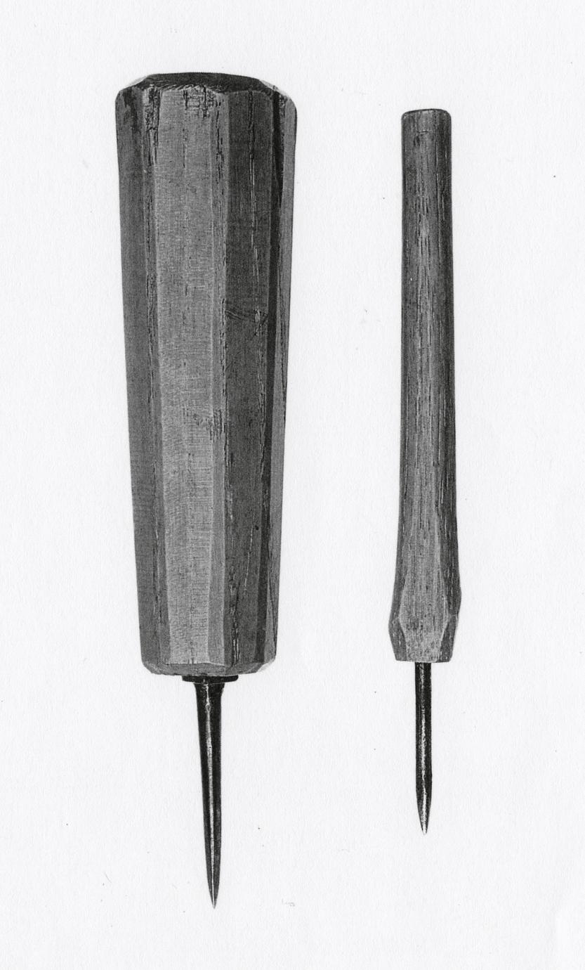
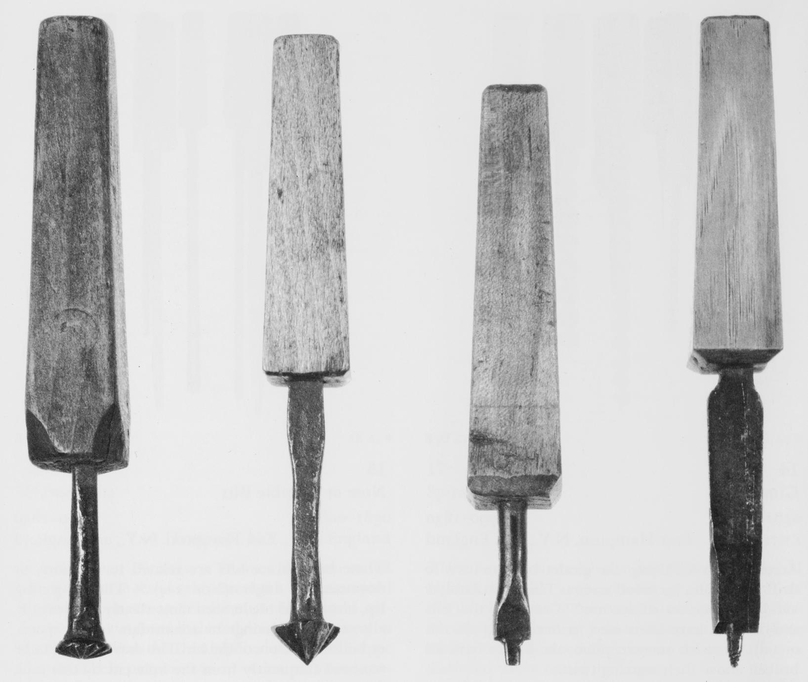
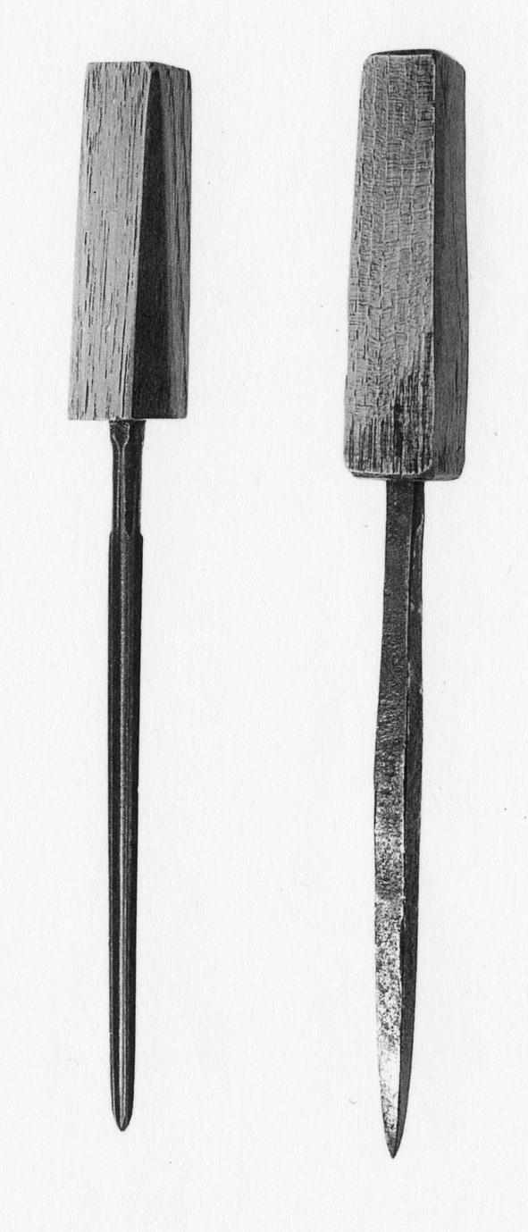
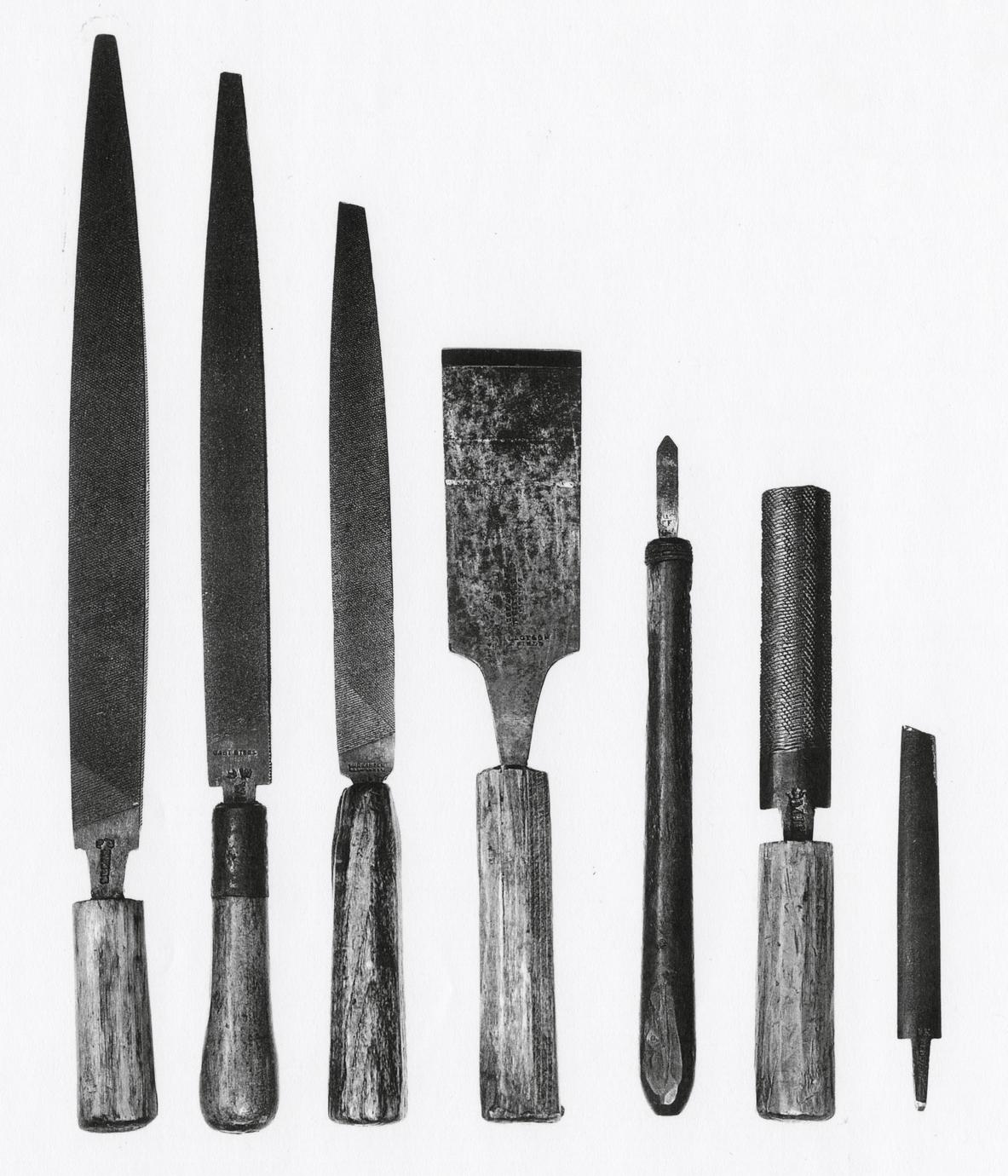
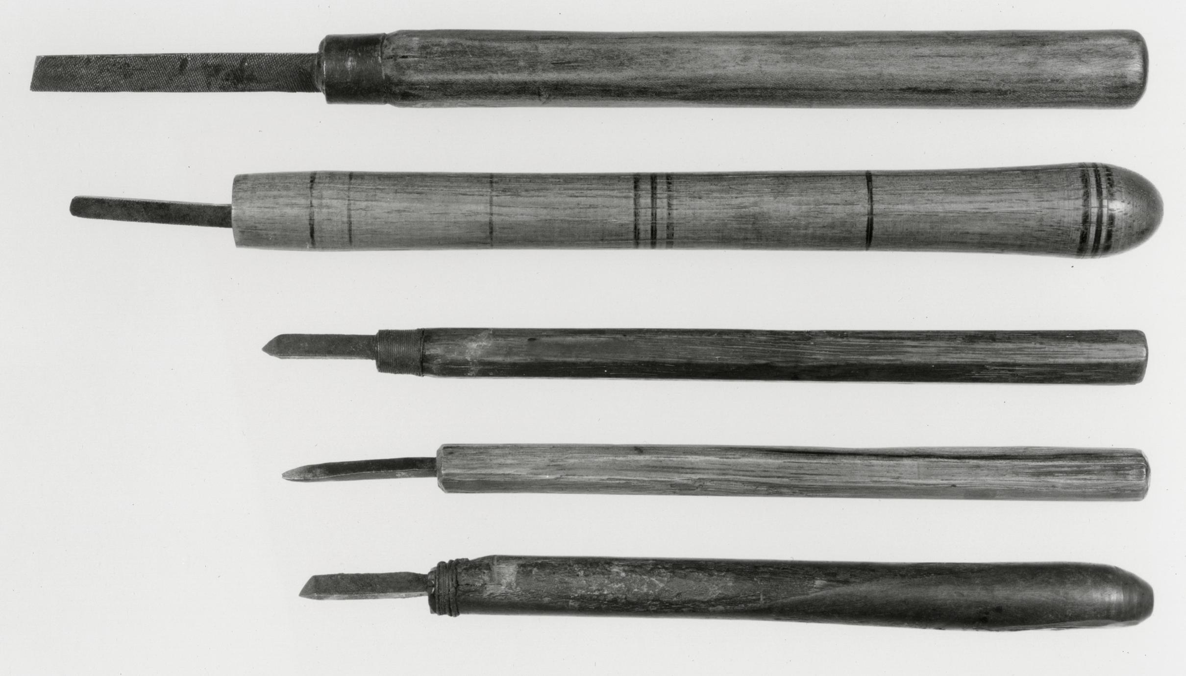
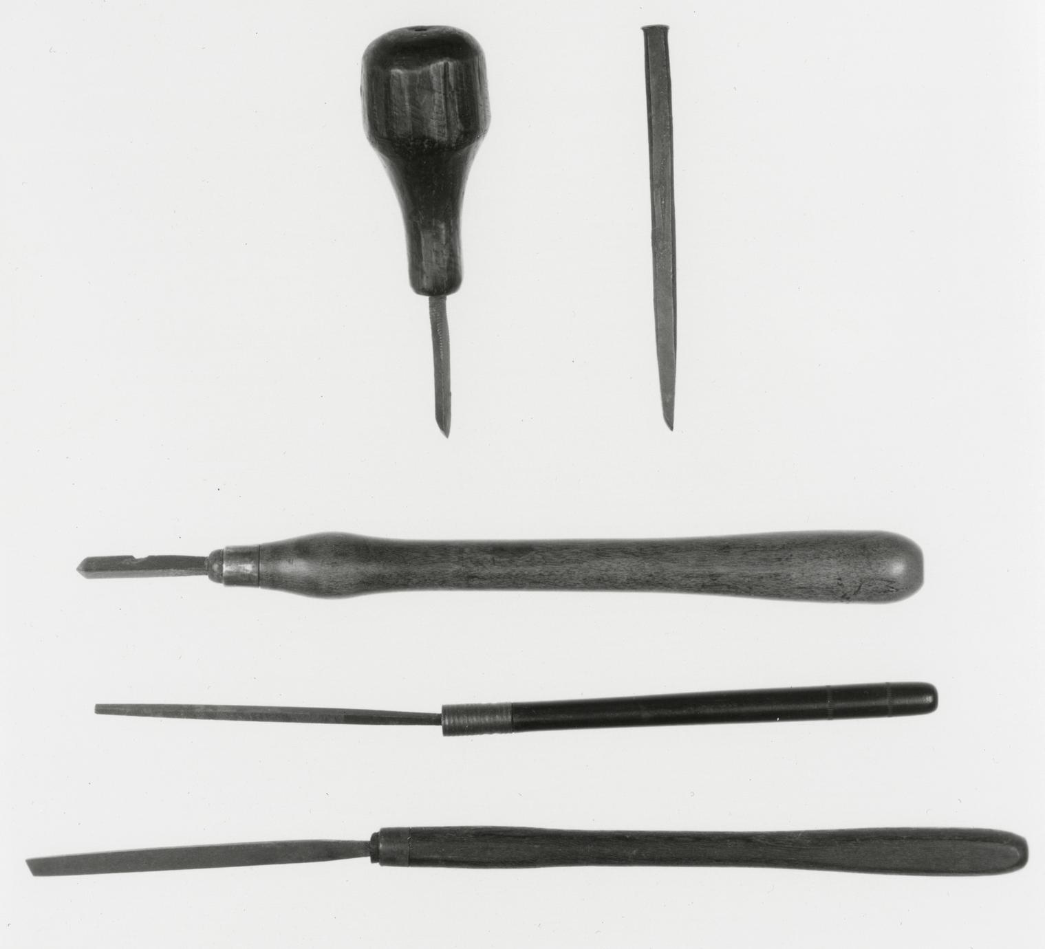
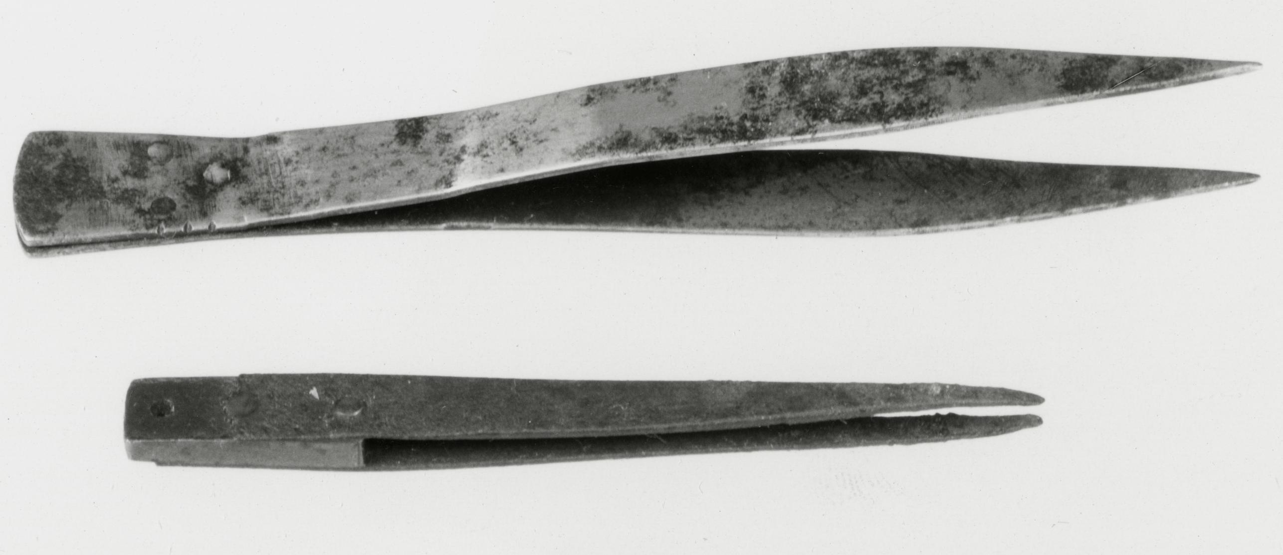
AWLS
6
Bradawls
1800–1840 New York City or East Hampton, N.Y.
6 A, B
Awls were owned by a variety of craftsmen. The
bradawl with its cylindrical shank and chisel-shaped
edge was used by joiners and carpenters.23
Moxon described this tool as a "Pricker" and stated
that in "vulgar usage" it was called an "awl."24 The
term "bradawl" was certainly applied by the early
nineteenth century, being used in Joseph Smith's
Explanation or Key, to the Various Manufactories
of Sheffield (1816), Nos. 546 and 547.
Woodworkers used the bradawl to push aside
wood fibers without splitting them. This was especially
important to rural craftsmen like the Dominys
in applying decorative moldings to cabinetwork
and in attaching the moldings with sprigs. The tool
was also useful in making starting holes for the
flat-ended screws in use during the eighteenth and
early nineteenth centuries. It came in assorted sizes,
as evidenced by the fact that four other bradawls,
larger and smaller than the two examples illustrated,
were included in the Dominy Tool Collection.25
Bradawl A was intended for heavier work; a
square hasp at the juncture of the shank and handle
prevents the blade from being pushed upward
into the handle under pressure. The device is illustrated
p. 49
in an English tool catalogue of about 1818
with a circular, tapered, belaying-pin-shaped handle.26
The octagonal-shaped handle, favored by the
Dominys for tools dating about 1790 to 1810, probably
places A about a generation earlier than B.
Two scribe, or scratch, awls used by the Dominys
to mark the surface of wood with guide lines are
not illustrated in this catalogue. With thin cylindrical
shanks tapering to a sharp point, they resembled
a modern ice pick. In the Dominy shop they were
probably referred to as "marking awls."27
Description A: Length, 6½. Steel blade; American
white-oak handle. B: Length, 5¾. Steel blade;
hickory handle. Both probably purchased by Nathaniel
Dominy V. Museum accessions: 57.26.132,
57.26.592.
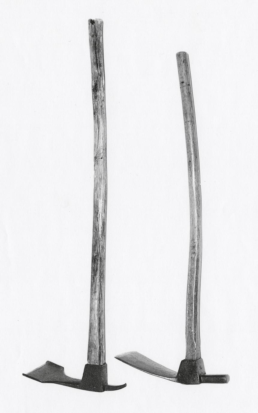
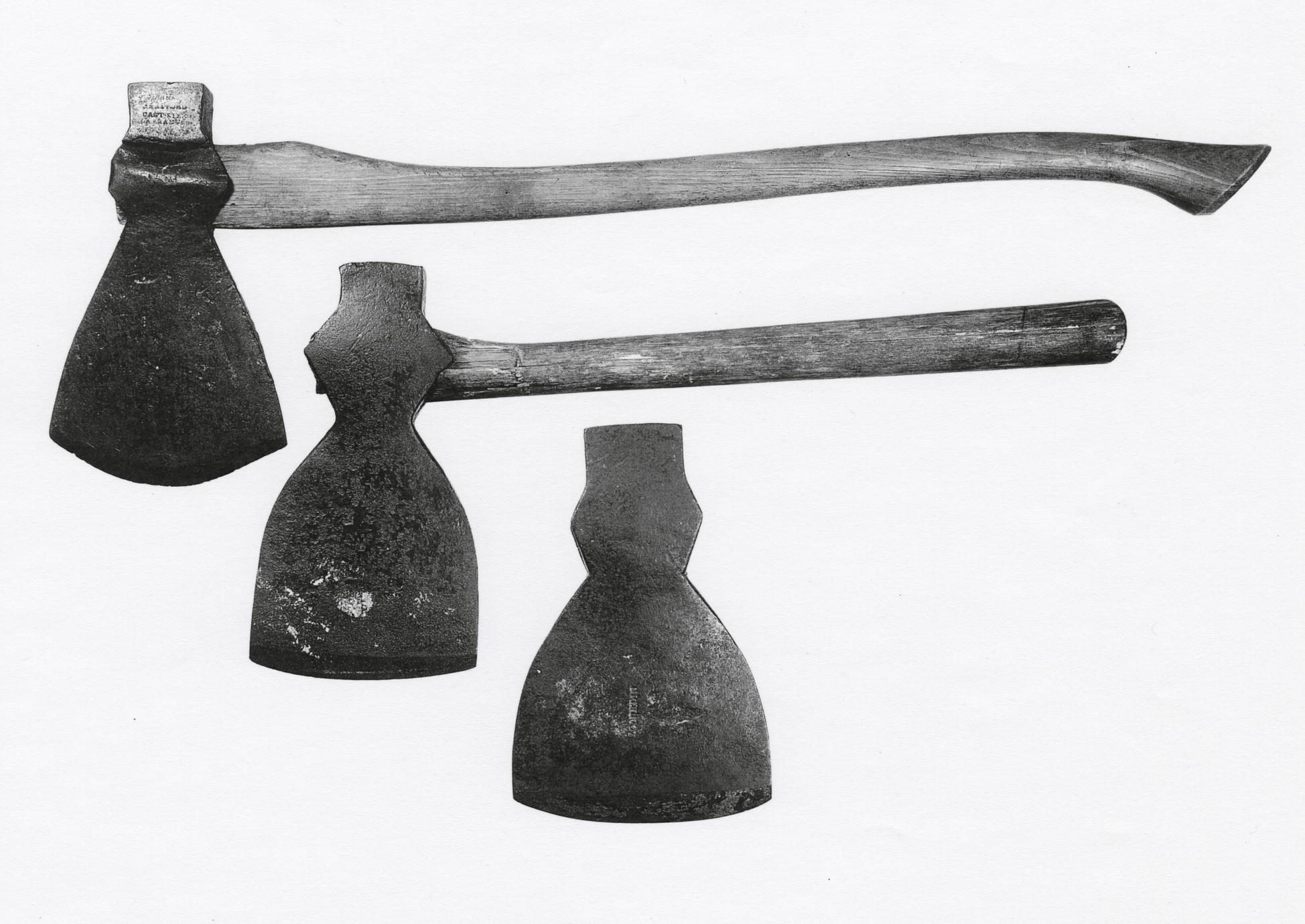
AXES
7
Broadaxes
1800–1850 America or England
7 A (top), B, C
It is evident from four surviving broadaxes that
earlier examples owned by Nathaniel Dominy IV
had been repaired too often to be of further use to
Nathaniel V. Between 1786 and 1805 their manuscript
accounts record at least ten instances of
"mending" or "new-laying" an edge on axes, including
five specific references to broadaxes.
Many modern authors regard the broadax as a
specific chisel-edged tool, "more than twice the size
of a felling axe," "used for hewing round logs into
square beams."28 The Dominys and their contemporaries,
however, apparently used the term "broad
axe" for a wide range of large axes of diverse size,
shape, function, and origin. Apparently the Dominys
owned more than one size of broadax, because
in 1805 Abraham Hedges, Jr., a blacksmith, was
credited with 1 shilling to "Harden &c Sm1 Broad
Ax," a clear implication that at least one of their
other broadaxes was larger.
An eighteenth-century book written by Edward
Hoppus to aid estate appraisers in valuing objects
for inventories lists "Four sorts of Felling Axes"
from 1 shilling 5 pence to 2 shillings, "Four sorts of
House Axes" from 2 shillings 6 pence to 3 shillings
6 pence, and "Four sorts of Lopping Axes" from 17
shillings to 24 shillings a dozen.29 Unfortunately,
these axes are not described or pictured. The list
may have been chiefly representative of the early
eighteenth century because later English tool catalogues,
for example, Joseph Smith's (1816) or Cutler
and Company's (about 1833 to 1837), show
twenty-four and twenty-three different types. At
least one catalogue shows a group of ax heads similar
to those of the Dominys' under the heading of
"Carpenters Broad Axes."30
Eighteenth- and early-nineteenth-century craftsmen's
use of a general term for a group of multipurpose
axes makes it difficult to determine how the
Dominys' axes were used. There are clues present,
however, that afford some clarification. The
broadax with the curved handle (A) was probably
used to fell trees. Shortly before 1808 W. H. Pyne
shows English woodsmen using this type of ax, as
well as the heavier wedge type, for "lopping off
branches from timber."31 Perhaps "lopping ax"
would be a better term to describe it. Its blade is
knife edged, the eye is symmetrical, and the replacement
handle is that of a late-nineteenth- or early-twentieth-century
felling ax. The nature of the
handle suggests that Nathaniel Dominy VII
(1827–1910) or Charles M. Dominy (1873–1956)
continued to use it for the purpose for which it was
originally made. The heavy poll is split near the
eye, an indication of heavy use. On it is stamped
COLLINS / HARTFORD / CAST STEEL /
WARRANTED. Collins and Company, founded in
1826, were the first to supply American markets
with cast-steel axes, and they also made other edge
tools at their Connecticut plant.32 This ax, therefore,
was probably made in the second quarter of
the nineteenth century.
The ax in the center of the picture (B) was used
for hewing or squaring logs into beams. It is chisel
p. 50
edged (bezeled on one side only), the rear side of
the eye is thicker than the side shown, and the
handle is bent at an angle to protect the user's hand
from grazing against timber being hewn. Its characteristics
fit the definitions of a broadax given by
Edward Knight and Henry Mercer.33 The handle is
most likely original, and the blade of iron with steel
facing indicates probable origin in the first quarter
of the nineteenth century.
An ax like C is referred to by Mercer as a "Knife-Edged
Broad Axe." It has a perfectly symmetrical
eye to receive a straight handle and a cutting edge
bezeled on both sides of the blade. It is identical,
however, to a type described as a "Kent" ax in
Joseph Smith's tool catalogue and is very similar to
a Kent ax shown in Wildung.34 This tool would
have been useful to the house carpenter and millwright
for hewing beams and rafters and to the
wheelwright for rough-shaping stock. Since Nathaniel
Dominy V practiced all three crafts, this would
have been a particularly useful ax. Its blade is
stamped I. CONKLIN, probably the name of the
firm that made it in the second quarter of the
nineteenth century.
One other broadax used by the Dominys has
survived (57.26.284). It is knife edged and was
probably a felling ax; its blade, stamped J. FORDHAM
/ SAG HARBOR / CAST STEEL /
WARRANTED, measures 12¼ by 6½ inches. All
the broadaxes discussed here fit into the category of
bench axes commonly used in the early years of this
century. Axes of the shape pictured, with cutting
edges from 4 to 7½ inches and single or double
beveled, were called "Bench Axes" by Sargent and
Company. Their "Broad Axes" had cuts ranging
from 11 to 13 inches and were available in "Western"
or "Pennsylvania" patterns. In 1863 the Douglas
Axe Manufacturing Company, East Douglas,
Massachusetts, made broadaxes in "New England,
New Orleans, Ohio & Western," and "Pittsburgh"
varieties.35 The precise terminology applied to hand
tools, as well as specific functions, still presents a
largely unresolved problem.
Description A: Handle length, 32¼; blade
length, 11; blade height, 6¾. Hickory handle (replacement);
cast-steel blade stamped COLLINS /
HARTFORD / CAST STEEL / WARRANTED.
B: Handle length, 22⅞; blade length, 11½; blade
height, 6¼. Hickory handle; iron blade with steel
face. C: Blade length, 10⅞; blade height, 7¼. Cast-steel
blade stamped I. CONKLIN. All probably
purchased by Nathaniel Dominy V. C, Museum purchase
from Nathaniel M. Dominy, 1957. Museum
accessions: 57.26.231, 57.26.82, 57.80.3.
p. 51
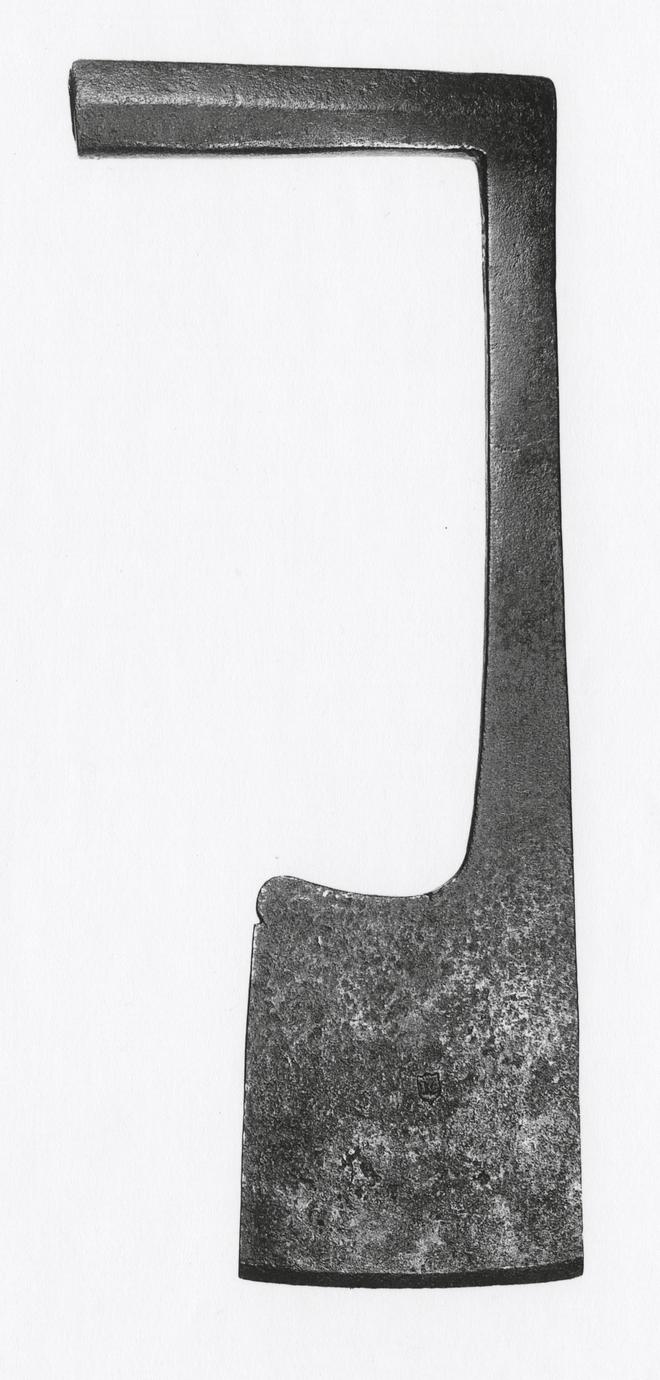
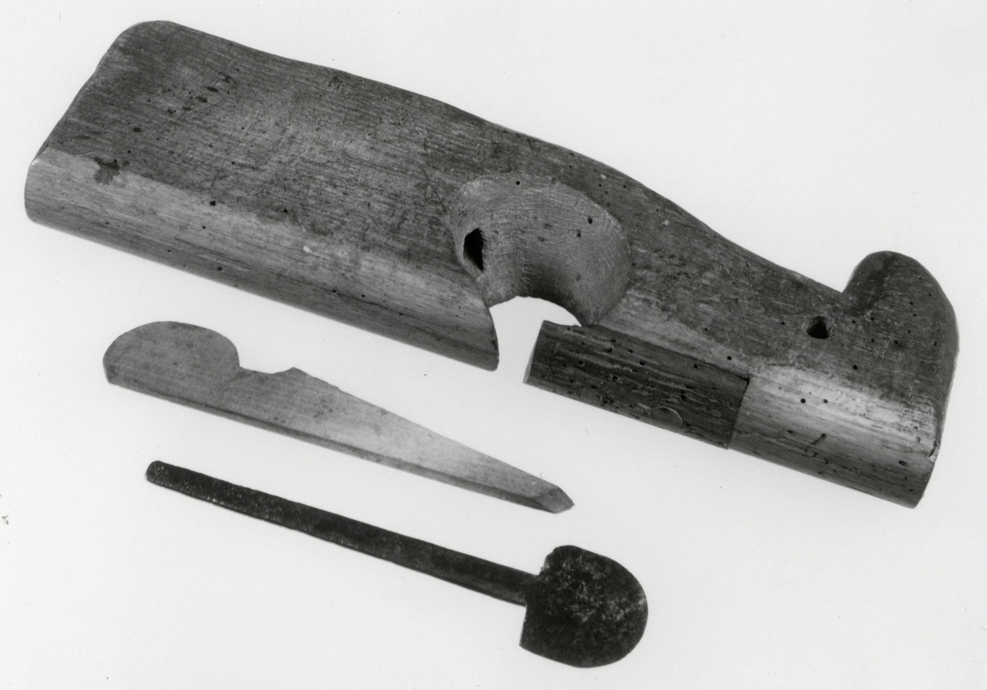
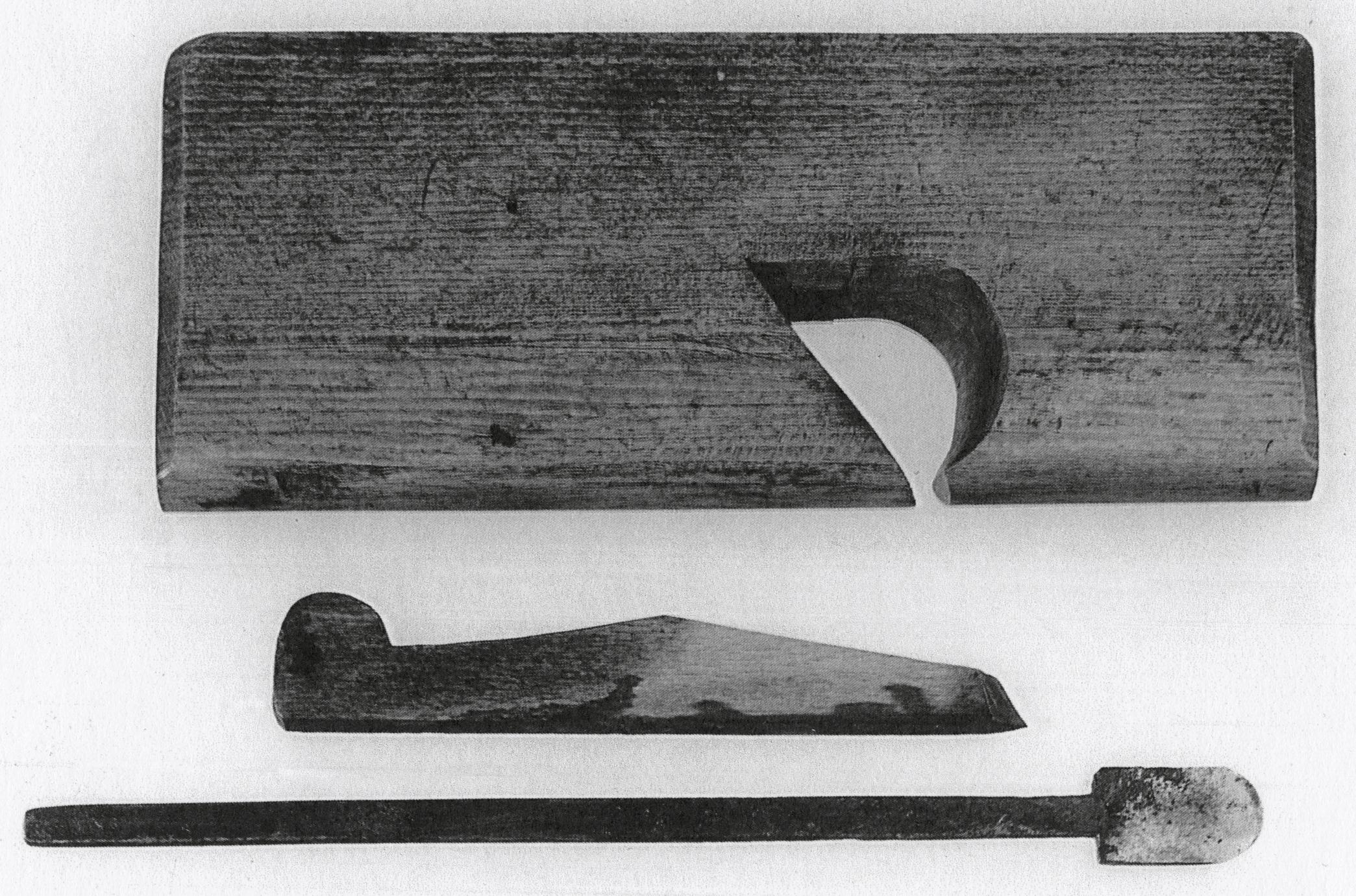
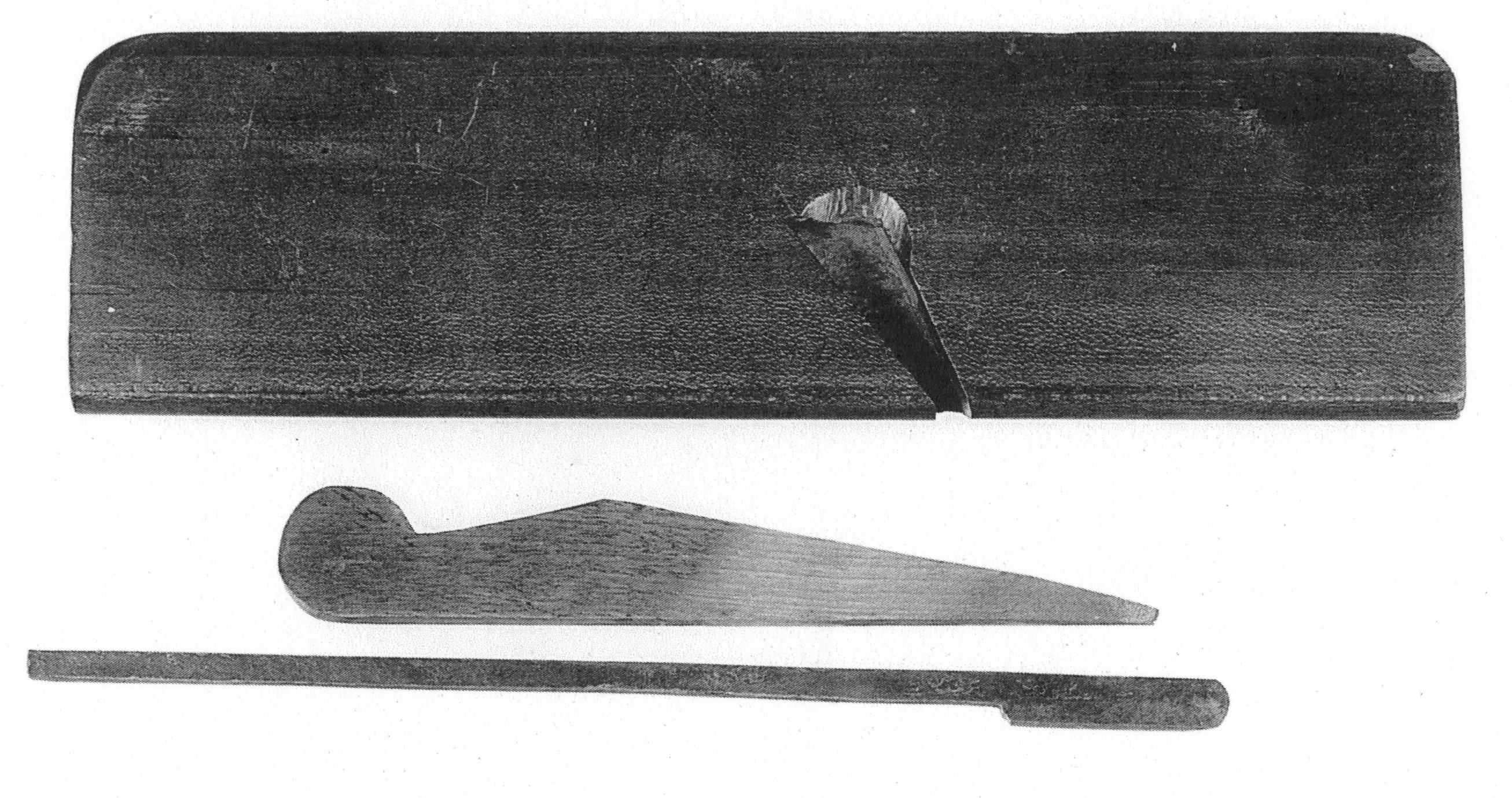
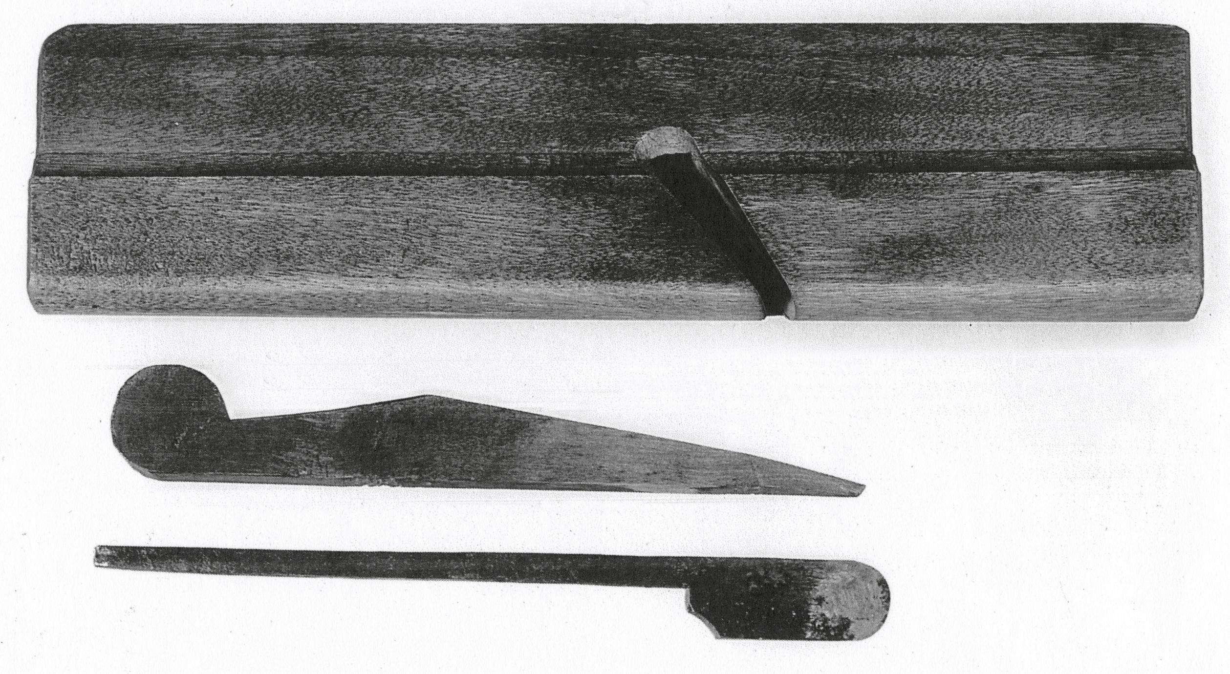
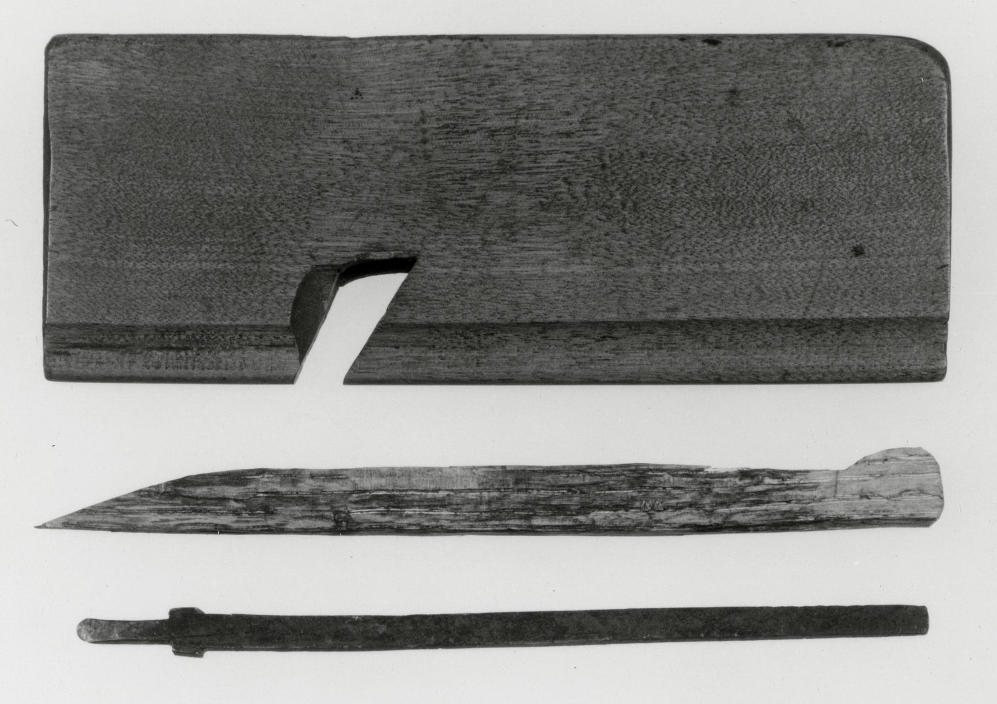
8
Carpenter’s Paring or Socket Ax
1725–1750 Probably Holland
8
This unusual ax has defied classification. No illustration
or description of a similar tool has been
found, and no positive identification could be given
by members of the Early American Industries Association
at their fall meeting in 1959 or in 1964
when they met at the Hagley and Winterthur
Museums.36 This ax would have been useful to carpenters,
shipwrights, and wheelwrights. The Dominys
did very little ship making or repairing, however,
and it was probably used by them for carpentry
or wheelwright work.
Plate I of the section of Diderot's Encyclopédie
illustrating the work of the wheelwright shows a
"beginning" or "fitting" ax (Illus. XV), which evidently
made the first rough cuts before an adz was
used to produce a curved surface on wood stock.37
The shank of the Dominys' ax is much longer,
however, and the two forms are probably unrelated.
It has been suggested frequently that this tool may
have been used as a mortising ax or that it was used
to trim mortises.38 If so, the cut would be quite
wide, almost 6⅝ inches, and very deep because of
the great length of the shank and blade, 23¼
inches. There is no evidence that the curved area
just above the decorative notch at the left of the
blade, or any other part of the tool, has ever been
struck. Instead, all evidence of use appears around
the chisel edge and at the opening in the iron shaft
(top left) into which a handle was fitted.
The bearer of the initials IC, stamped inside a
shield, has not been identified; but the stamp design
helps to date the ax as having been made in
the early eighteenth century. Nathaniel Dominy
III, the probable owner of the ax, is described in
deeds as "a carpenter," as discussed in Part One.
It has been suggested that this ax was used to
trim the edges of boards by "letting the ax drop of
its own weight, and twisting the handle from side to
side."39 It is true that the weight and balance of the
ax is concentrated in the blade so that, when lifted,
it would fall of its own accord.
In Der Odenwald (June 2005), pages 65-75, Professor
Karl Azzola illustrates very similar carpenter’s axes on
late Medieval stonecrosses, dating ca. 1500, near
Hesselbach, Hesseneck Township, Odenwaldkreis, Germany.
The Joseph Greber Collection, Decorative Arts Photographic
Collection, Winterthur Museum Library, contains a photograph
of a wood-carved drawing printed in a Carmelite manuscript
at Vilvoorde, near Brussels, Belgium. It shows a carpenter
paring or truing-up the edges of a floor board. The
carpenter is using a tool identical to catalogue no. 8.
Letters to the author from Art Shaw, July 18, 1979, and
Edward Ingraham III, July 23, 1983, also confirm the tool
as a paring or socket axe.
Description Handle length, 9; overall length, 23¼; blade length,
7⅝; blade width, 6 9/16. Iron blade stamped IC
inside a shield. Probably purchased by Nathaniel
Dominy III. Museum accession: 57.26.280.
p. 52Illus. XV. Fitting or beginning ax ("Cognée emmanchée"). From Denis Diderot's Encyclopédie, III (Paris,
1763), "Charron," Plate I, Figures 1, 4.
p. 53
BENCHES
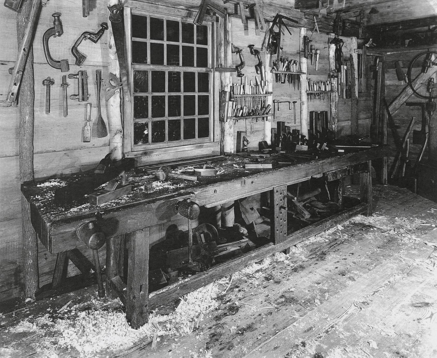
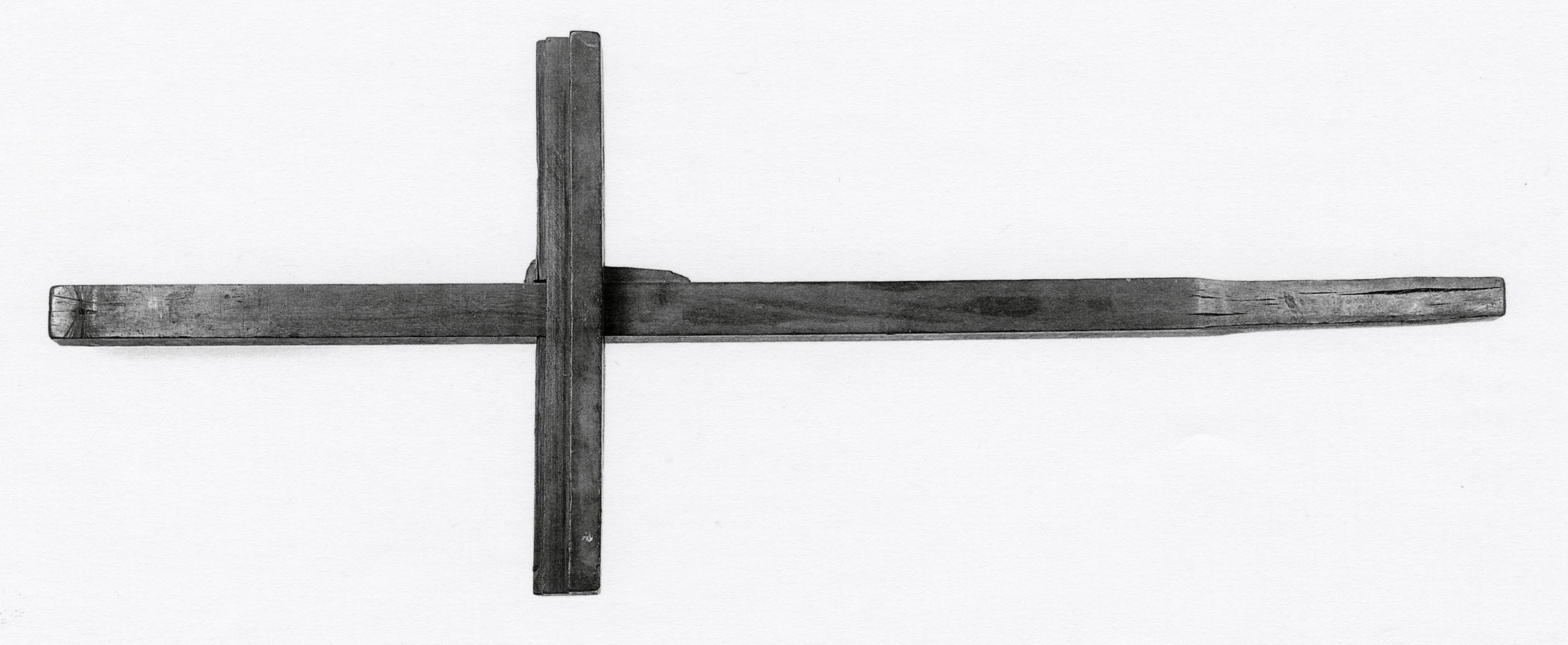
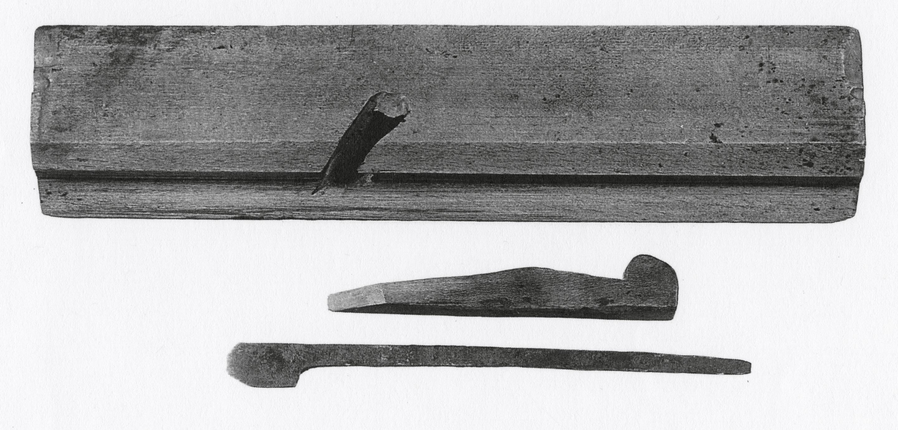
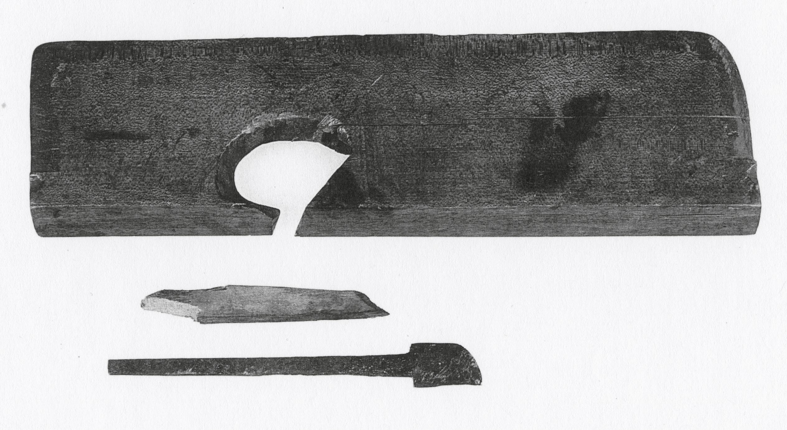
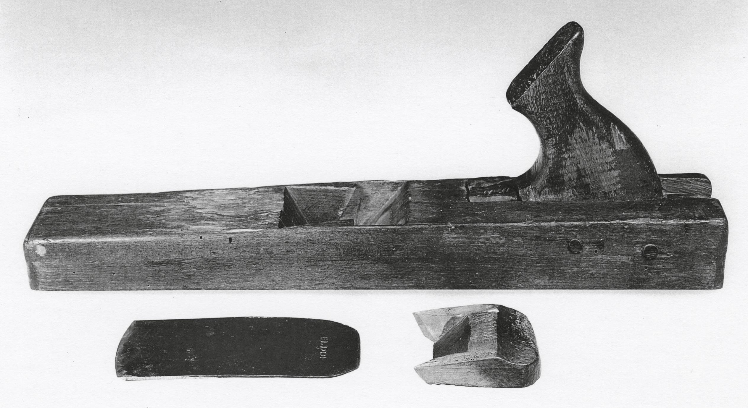
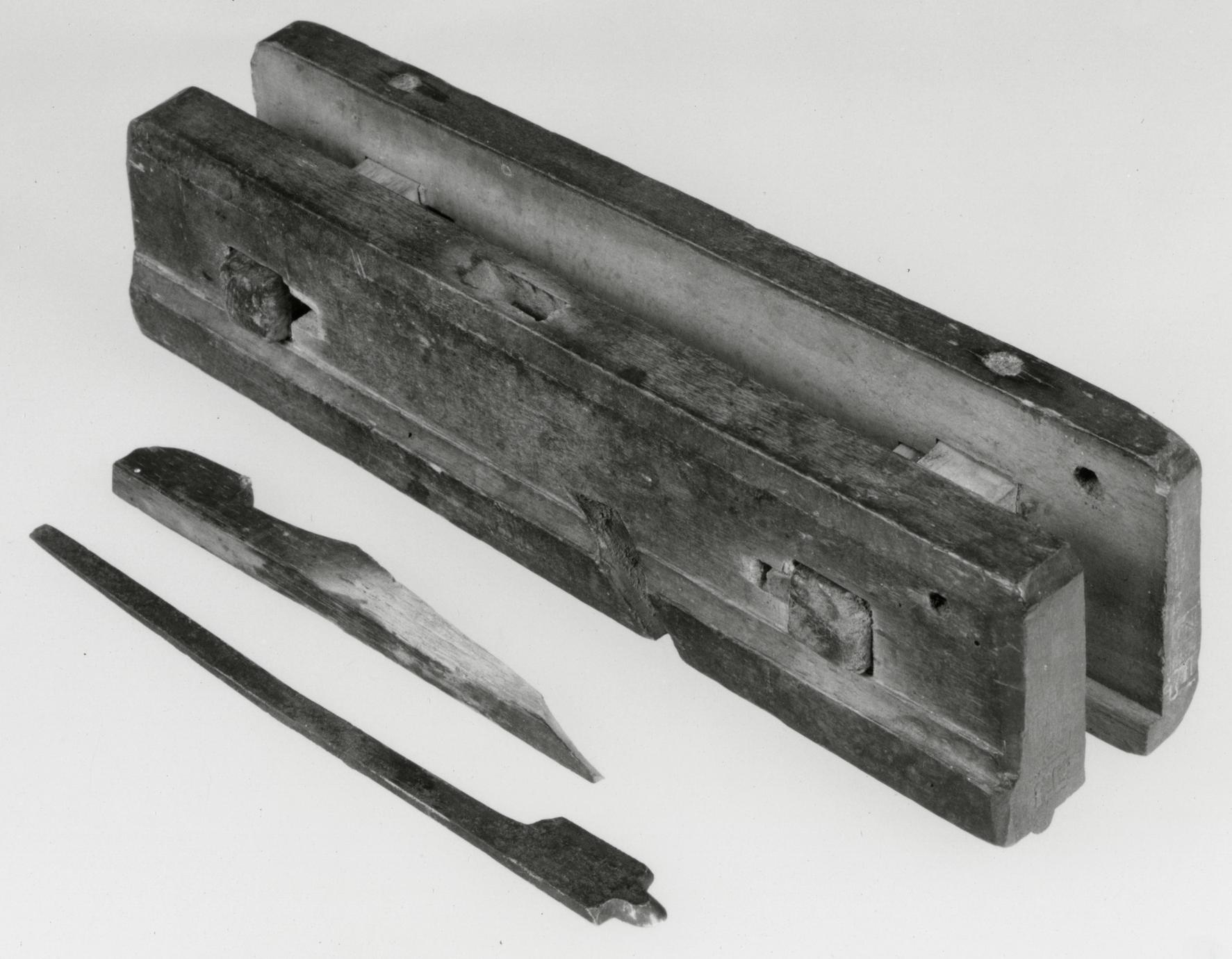
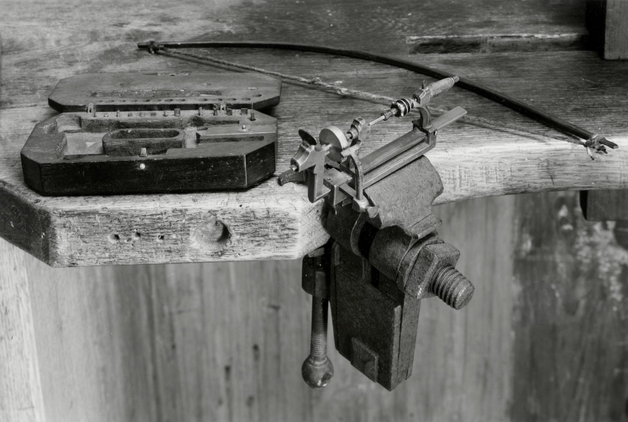
9
Bench or Workbench
1750–1775 East Hampton, N.Y.
9
This is a superb example of the eighteenth-century
joiner's bench. Its main surface is made from a solid
piece of red oak more than 12 feet long, 17½ inches
wide, and 5½ inches thick. A supplementary board,
10¾ inches wide and 1¾ inches thick, provides a
wider work surface. The window on the wall behind
the bench faced east, admitting light from the
rising sun and providing sufficient light for the
craftsmen to work into the early part of the afternoon.
Its location and size indicate that this was
undoubtedly the most important of the three
benches in the Dominys' woodworking shop. Nathaniel
Dominy III was a carpenter, and this bench
may have been in the shop when Nathaniel IV
began his career. For that reason, and because of
details of its construction, it has been dated in the
third quarter of the eighteenth century.
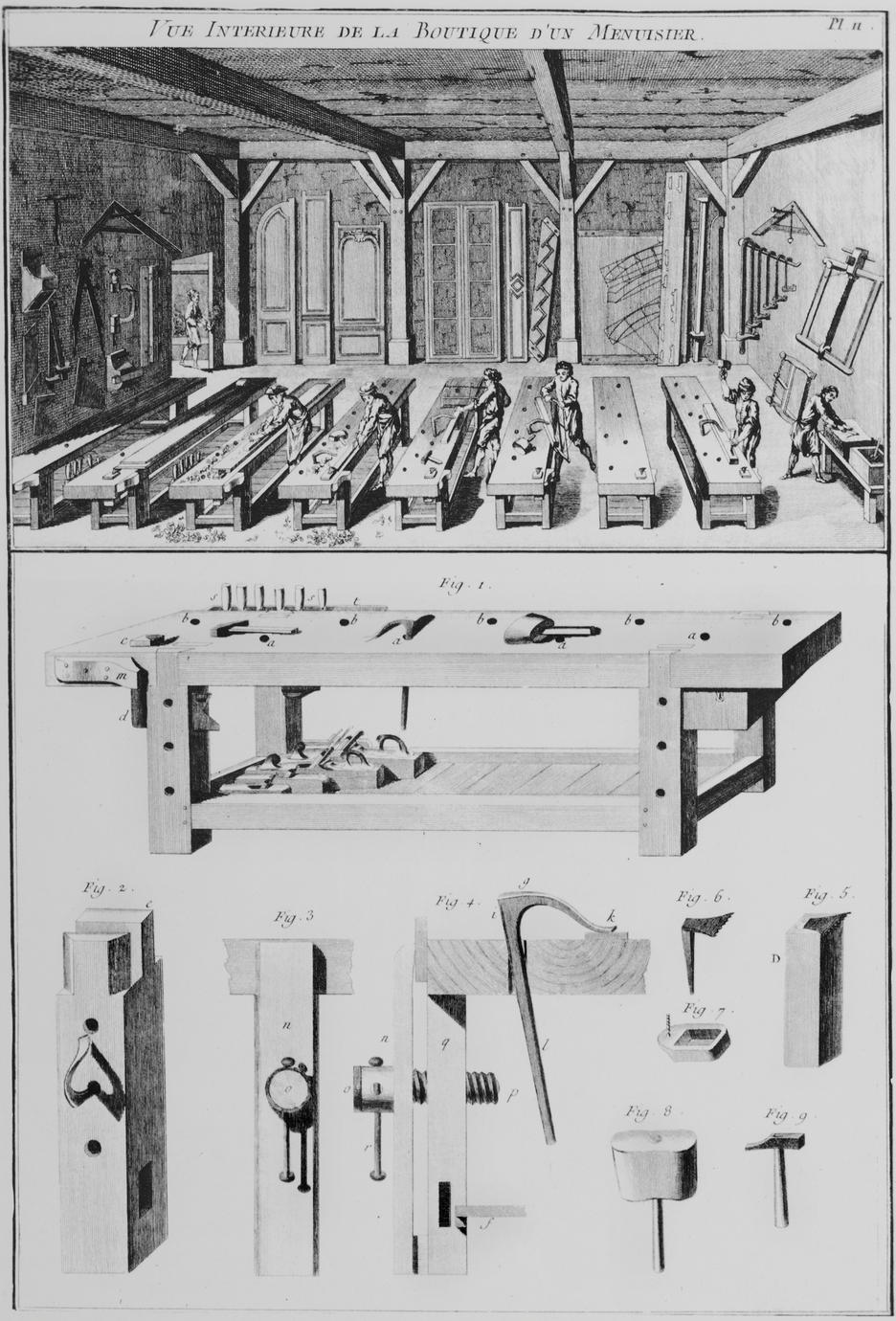
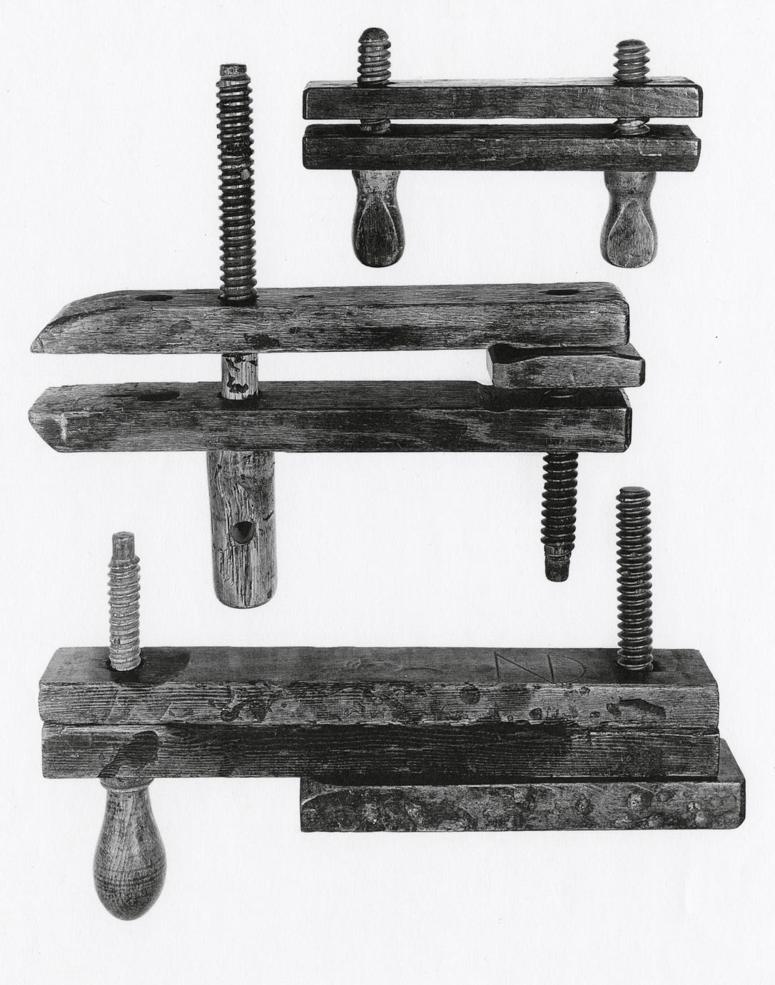
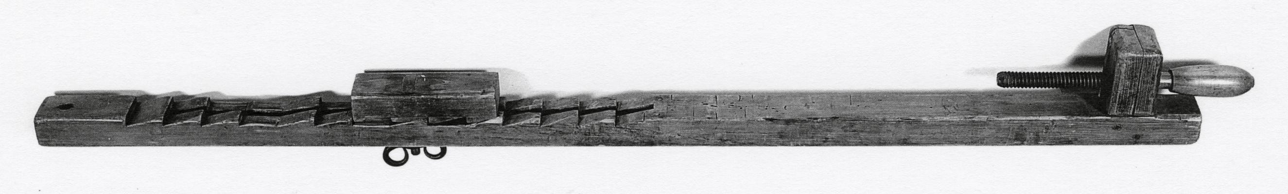
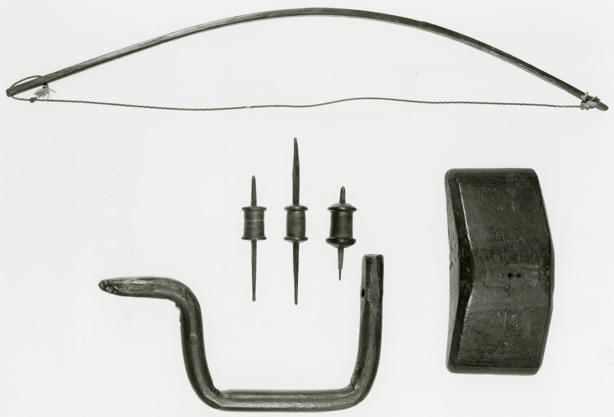
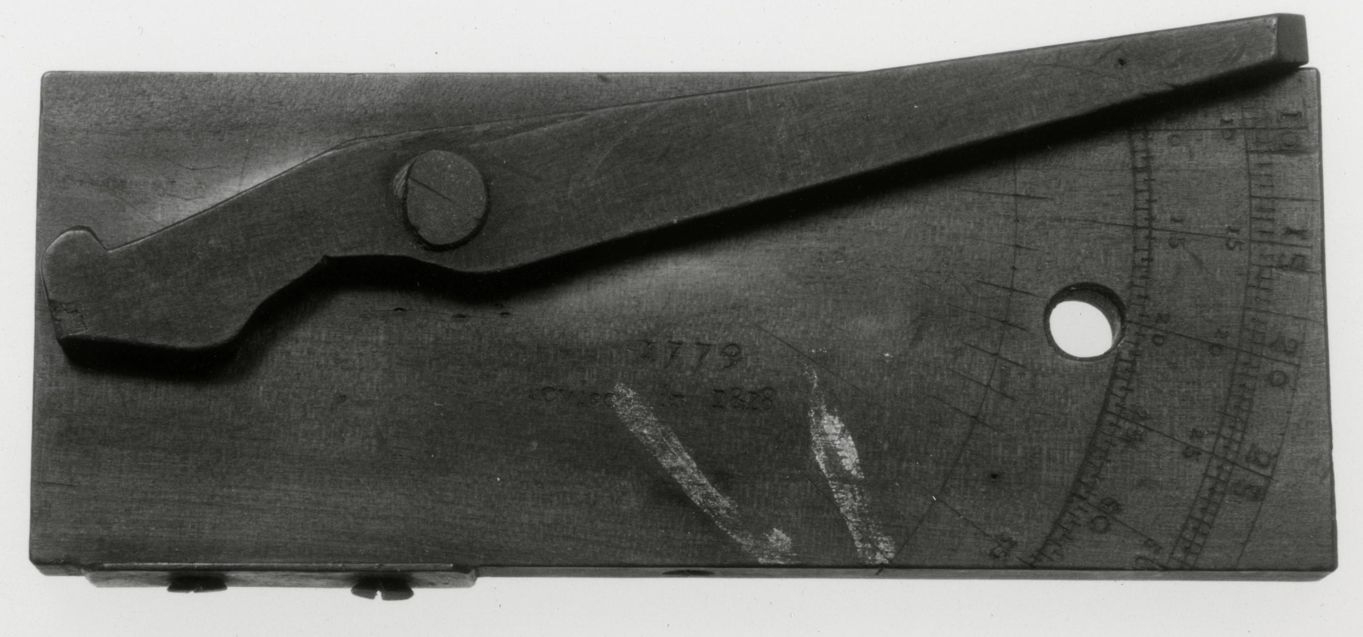
Moxon describes the workbench as a "tool," and
this was perhaps the most useful of all their tools
for holding and gripping boards being planed,
sawed, or shaped with a chisel. Several features of
the Dominys' bench are similar to those illustrated
by Moxon in 1703 and later by Roubo about 1769.40
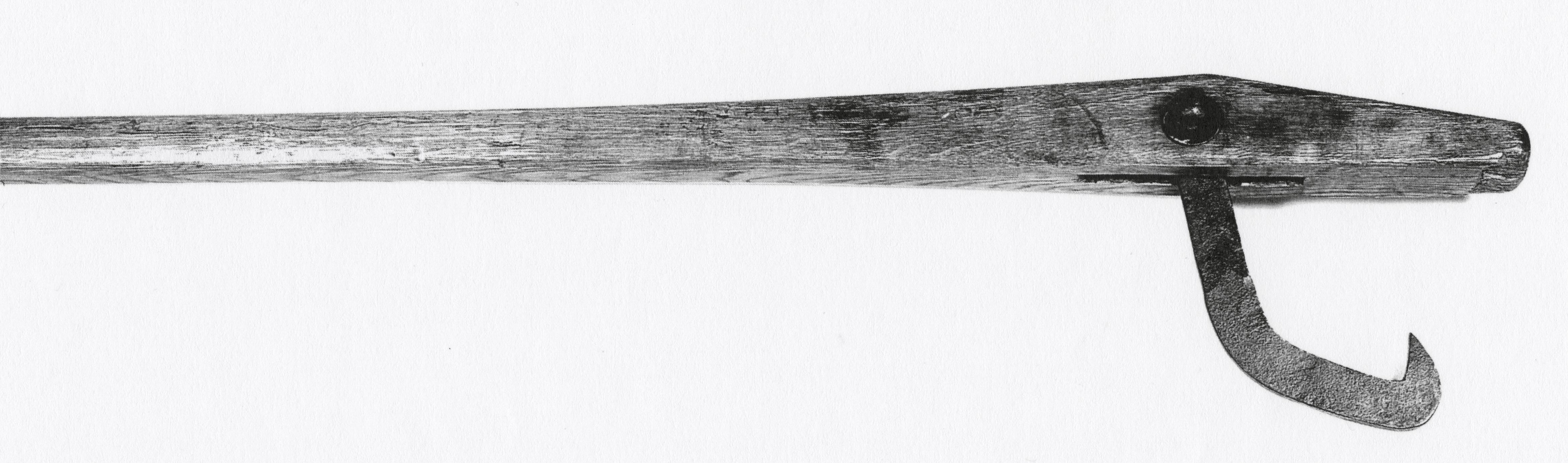
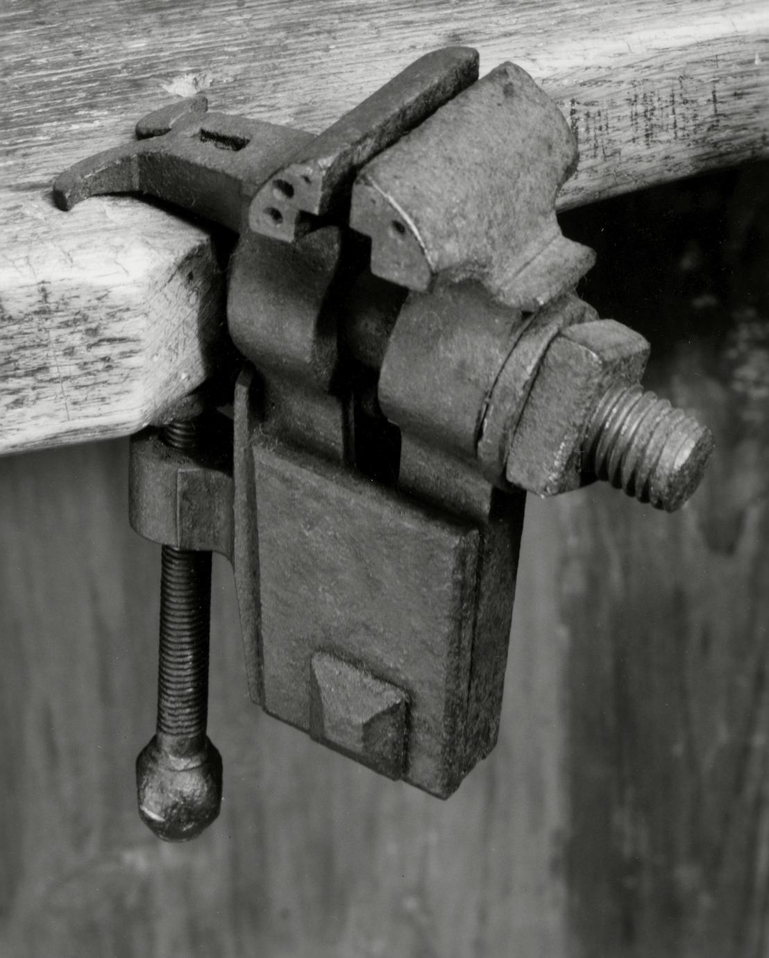
These include a board catch (between the mallet
and plane), called a "Hook" by Moxon. The serrated-edge
iron hook is imbedded in an adjustable,
rectangular wood block similar to that shown in
Figures 5 and 6 of a plate from L'art du menuisier
(Illus. XVI). A tap with a mallet served to raise or
lower its height. This device was used "to lay
Boards or other Stuff flat against, whilst they are
Trying or Plaining." Its function is clearly shown
on the benches of the two workmen at the left of
Roubo's view.
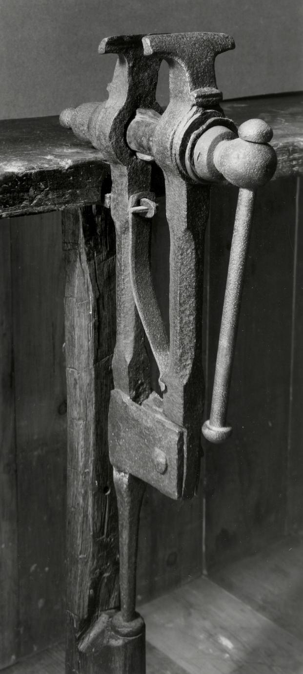
Moxon's bench employed either a single- or a
double-screw vise. The simple handgrip screws of
Moxon's example have been replaced on the Dominys'
p. 54Illus. XVI. Interior view of a woodworker's shop. From André Jacob Roubo, L'art du menuisier (Paris, 1769–1775),
III, Plate II.
p. 55
bench by large heads with turning handles. It
was still necessary for the Dominys to loosen the
vise board by hand because the screws apply pressure
on the "in" stroke only. When long boards
were fastened in the screw vise to square, or
"shoot," the edges or to place a molding on the
edge, it was necessary to support the end of the
board away from the vise to minimize its vibration.
Woodworkers usually solved this problem by boring
a series of holes into the legs of the bench. The
holdfast, or a peg, was inserted into the holes (see
Illus. XVI).
The Dominys used a sophisticated variant of this
practice with a board that slid on a 4-foot-long
track. This enabled them to vary the distance from
the vise according to the length of the board and
gave support precisely where needed. Between the
upper rail of the track and the bench drawers is a
grease container that pivots on a screw and can
easily be drawn out when needed. That useful device
is shown as Figure 7 in Roubo's plate.
In colonial America it was customary for a woodworker
to build his own workbench. In rural areas
it was not unusual for farmers or other noncraftsmen
also to need a bench, and on January 26, 1773,
Nathaniel Dominy IV billed Nathan Conkling, Jr.,
10 shillings for a "joiners bench." It was probably
small because on September 15, 1796, Nathaniel V
charged Jonathan Baker 7 shillings "To cut pair of
bench screws." A bench that cost only 3 shillings
more than "screws" could not have been very large.
Description Length, 148¼; height, 29½; depth,
28¼. All parts of red oak. Made by Nathaniel
Dominy III or Nathaniel Dominy IV. Museum accession:
57.26.367.
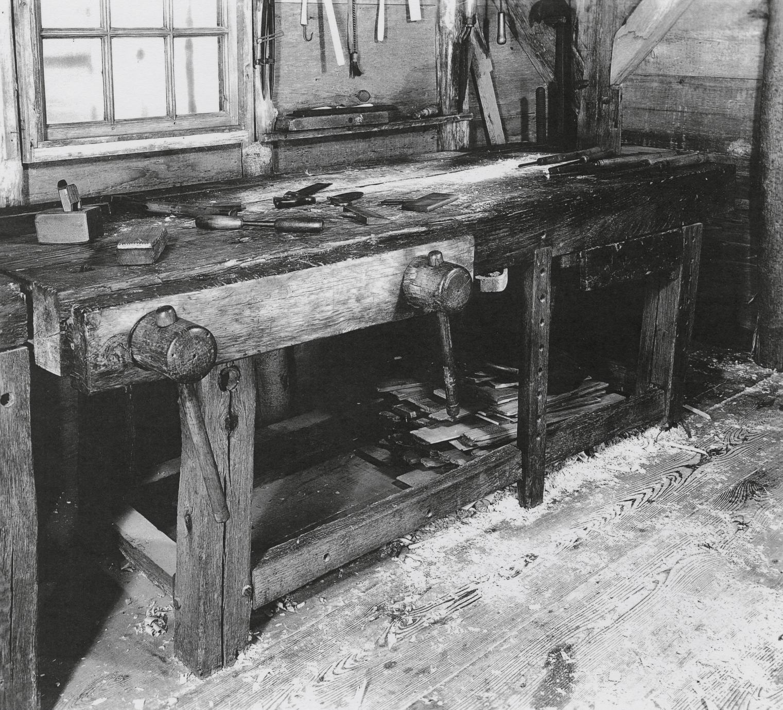
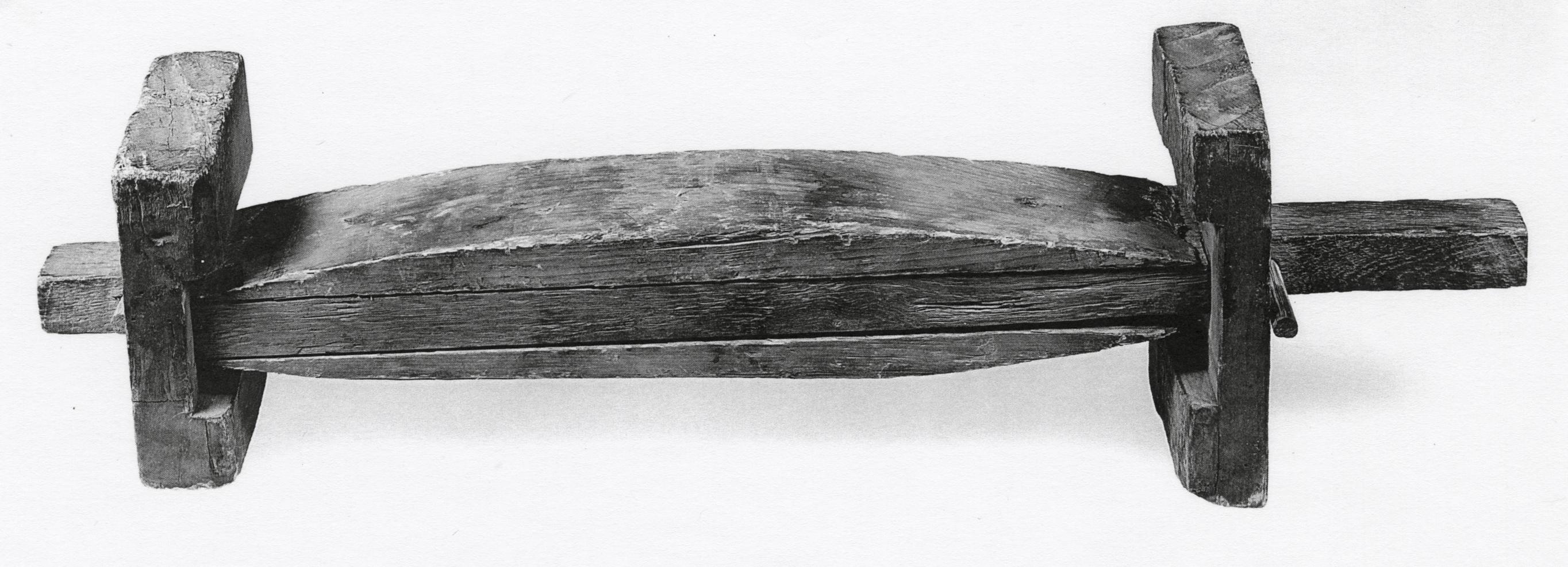
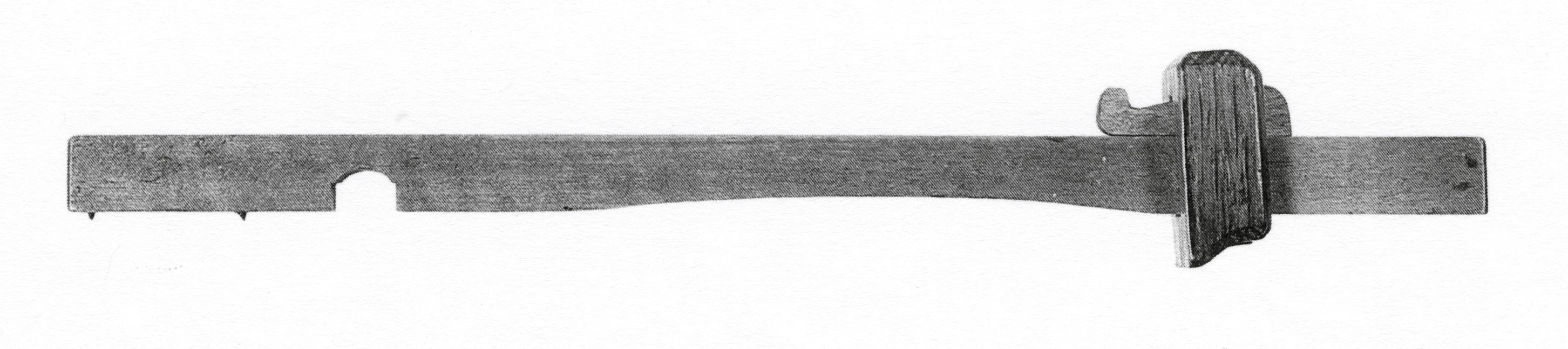
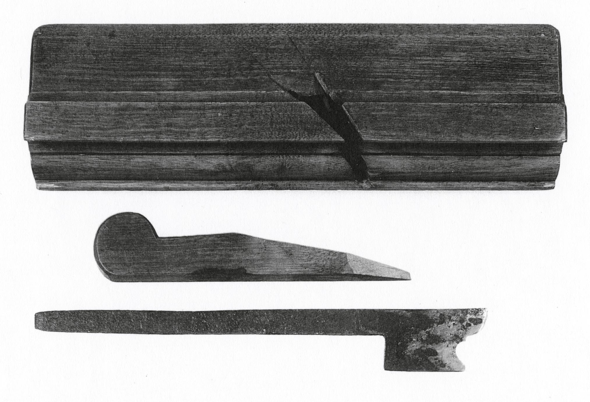
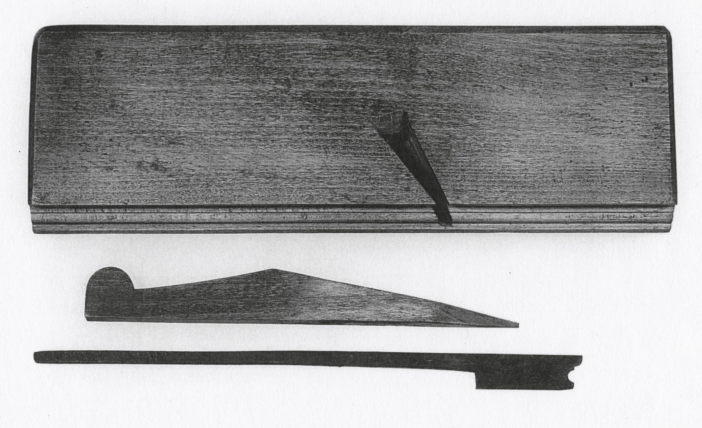
10
Bench or Workbench
1750–1775 East Hampton, N.Y.
10
On the west wall of the Dominys' woodworking
shop were two smaller workbenches, each placed in
front of a window to receive light from the midafternoon
and evening sun. The bench not illustrated
(57.26.368) is almost identical to this one except
that it is slightly larger, has a sliding board support,
and also has a hole bored in its top to receive a
holdfast.
It is possible that this example may be the oldest
of the Dominys' benches. The board supports are
stationary, as shown in Moxon, and the large hole
in the leg under the vise board may indicate that
p. 56
the bench originally had a single-screw vise
mounted vertically, as pictured by Moxon and
Roubo.41 At least one change was made in the
bench design: holes for supporting boards were
originally bored into the far leg of the bench. An
extra vertical board support, designed to accommodate
stock under six feet long, was obviously
fitted into the stretcher and bench top as an afterthought.
To the right of the vise board can be seen a
grease cup. The board catch, or "hook," has been
taken from its hole and placed between a plane and
a burnisher. Although the catch fits its hole snugly,
its height above the surface of the bench can be
easily adjusted with a few taps of a mallet. All three
benches are lower than the medium height of 32
inches mentioned by Nicholson and are not anywhere
near the waist-high height noted by Mercer
in his discussion of the carpenter's bench.42 This
might indicate that the Dominy craftsmen were
short. A more logical explanation is that much of
the work accomplished on the bench required the
application of arm and hand pressure—more easily
applied when the bench surface was lower. Even so,
modern craftsmen would be quite uncomfortable
leaning over these benches.
Description Length, 77¾; height, 28⅞; depth,
31. Red-oak top and legs; white-oak stretcher. Made
by Nathaniel Dominy III or Nathaniel Dominy IV.
Museum accession: 57.26.369.
p. 57
BITS
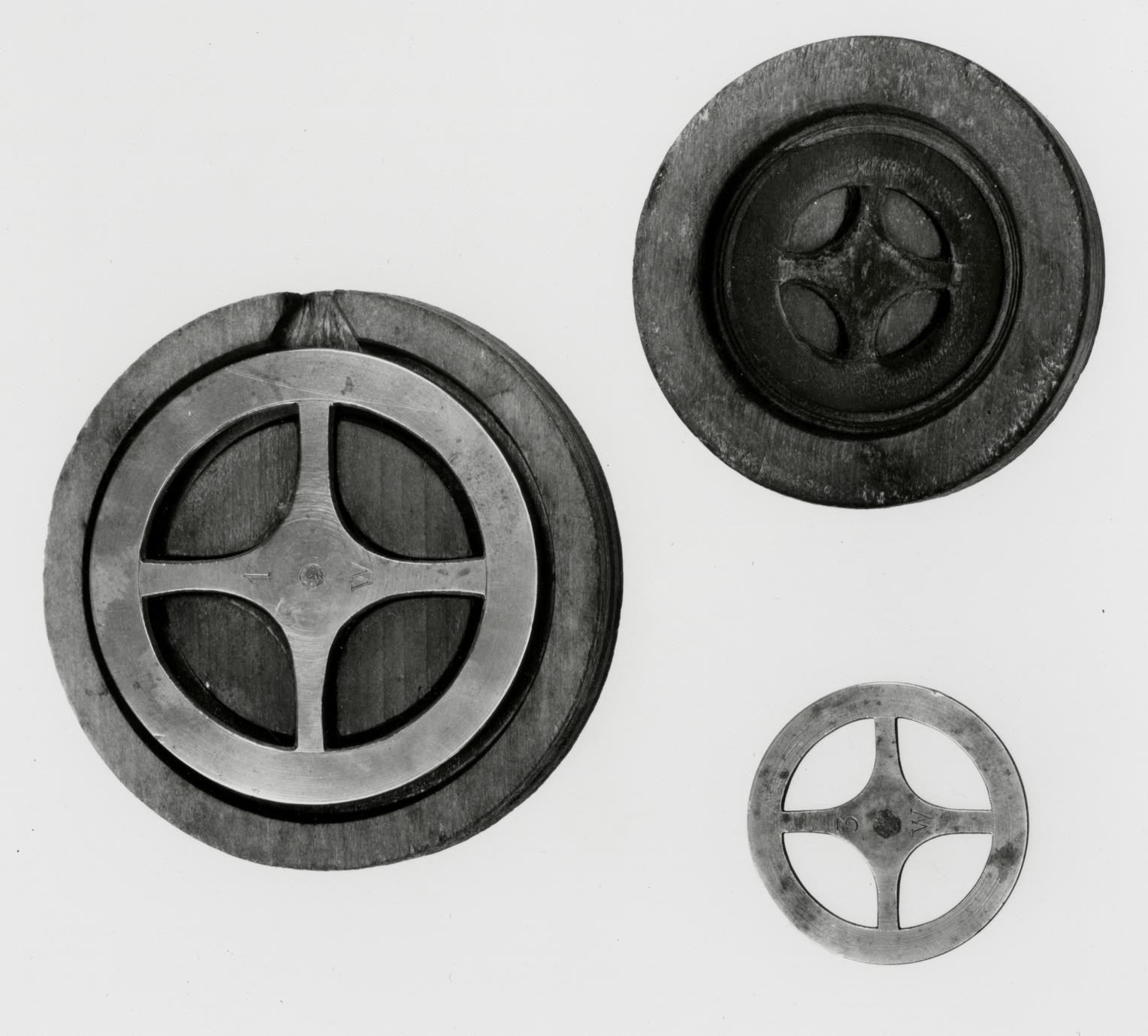
11
Button Bits
1800-1840 East Hampton, N.Y.
11 A, B, C, D
These button bits were used by the Dominys to
scribe, cut, and smooth bone, horn, and wood buttons.
Forced into a hand brace of the type shown in
Number 20, they were held in place by pressure.
Their outer spurs scored and cut the circumference
of the button. Sharp chamfered edges between the
spurs and center pin smoothed the button surface
just before the spurs cut through and released it.
Although they have been described as "button
bits," no mechanic's handbook or tool catalogue
published before the middle of the nineteenth century
depicts this form.43 The contemporary illustration
most like it appears in a French turner's manual
of 1792, where it is described as a form of
English center bit.44 It is shown without spurs and
is similar to C, which is stamped FD.
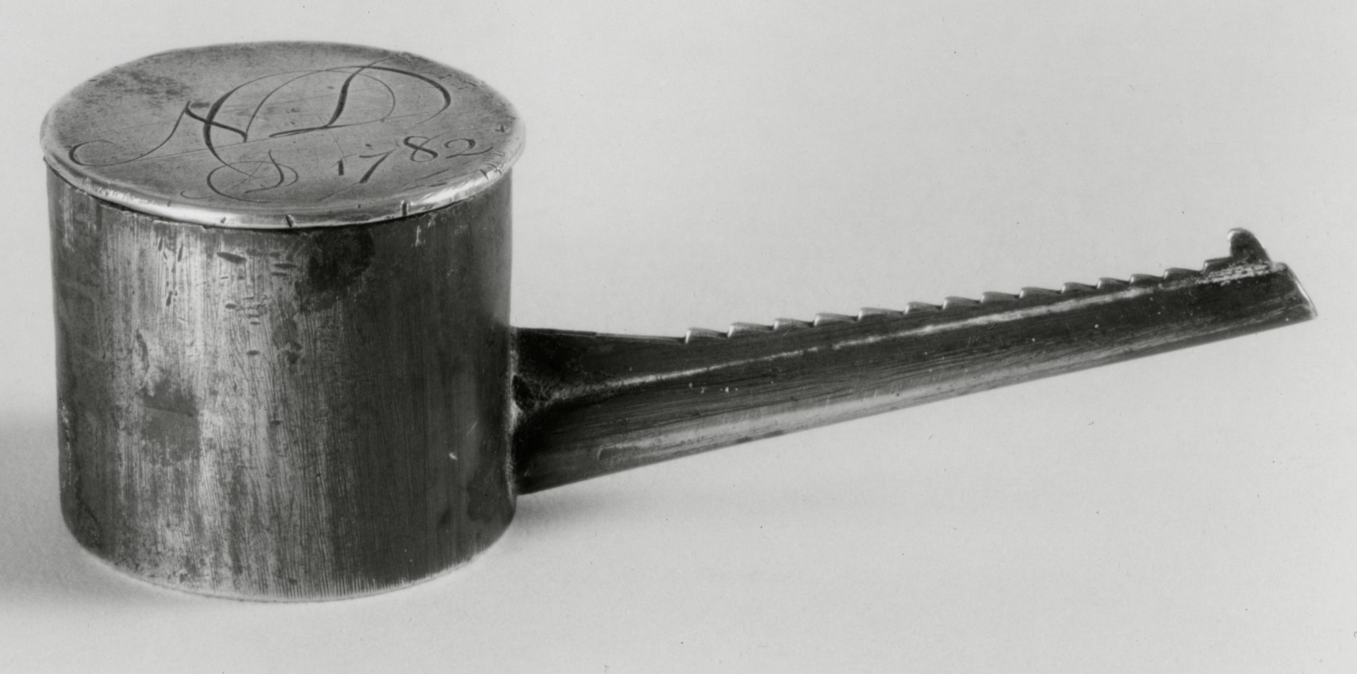
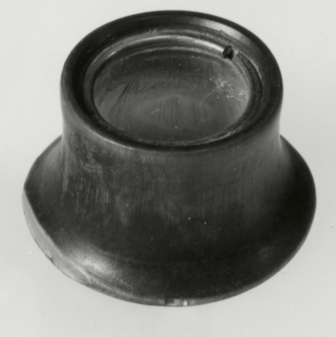
Between 1773 and 1822, Dominy accounts record the
making of 356 buttons and 1,708 button molds. The Oxford
English Dictionary describes the latter as wood disks
to be covered with cloth for buttons. Since the Dominys'
customers often paid for
their products with clothing, the bits were probably
used by the craftsmen to provide buttons for their
own use. The bit not shown has a cherry-wood
shank with a wrought-iron shaft and cutter.
Description A: Length, 5 3/16; bit diameter,
9/16. Soft-maple block; steel shaft and bit. B:
Length, 5½; bit diameter, 9/16. Birch block; steel
shaft and bit. C: Length, 6; bit diameter, 7/16.
Soft-maple block stamped FD; steel shaft and bit.
D: Length, 7 5/16; bit diameter, 19/32. Hickory
block; steel shaft and bit. A, B, and D probably
made by Nathaniel Dominy V; C made by Felix
Dominy. Museum accessions: 57.26.159, 57.26.156–157,
57.26.155.
p. 58
12
Chair, Pin, Quill, or Spoon Bits
1790–1830 East Hampton, N.Y., and England
12 A, B, C, D, E
In late-eighteenth- or early-nineteenth-century tool
catalogues, these bits are called "chair," "spoon,"
"quill, or "pin," interchangeably. Tool A, for example,
is described as a "chair" bit and was available
in ⅜- and ⅝-inch sizes.45 Although the end of
this bit is bent upward, its name describes its function
perfectly; it was used by the Dominys to drill
holes in chair stiles to receive the round tenons of
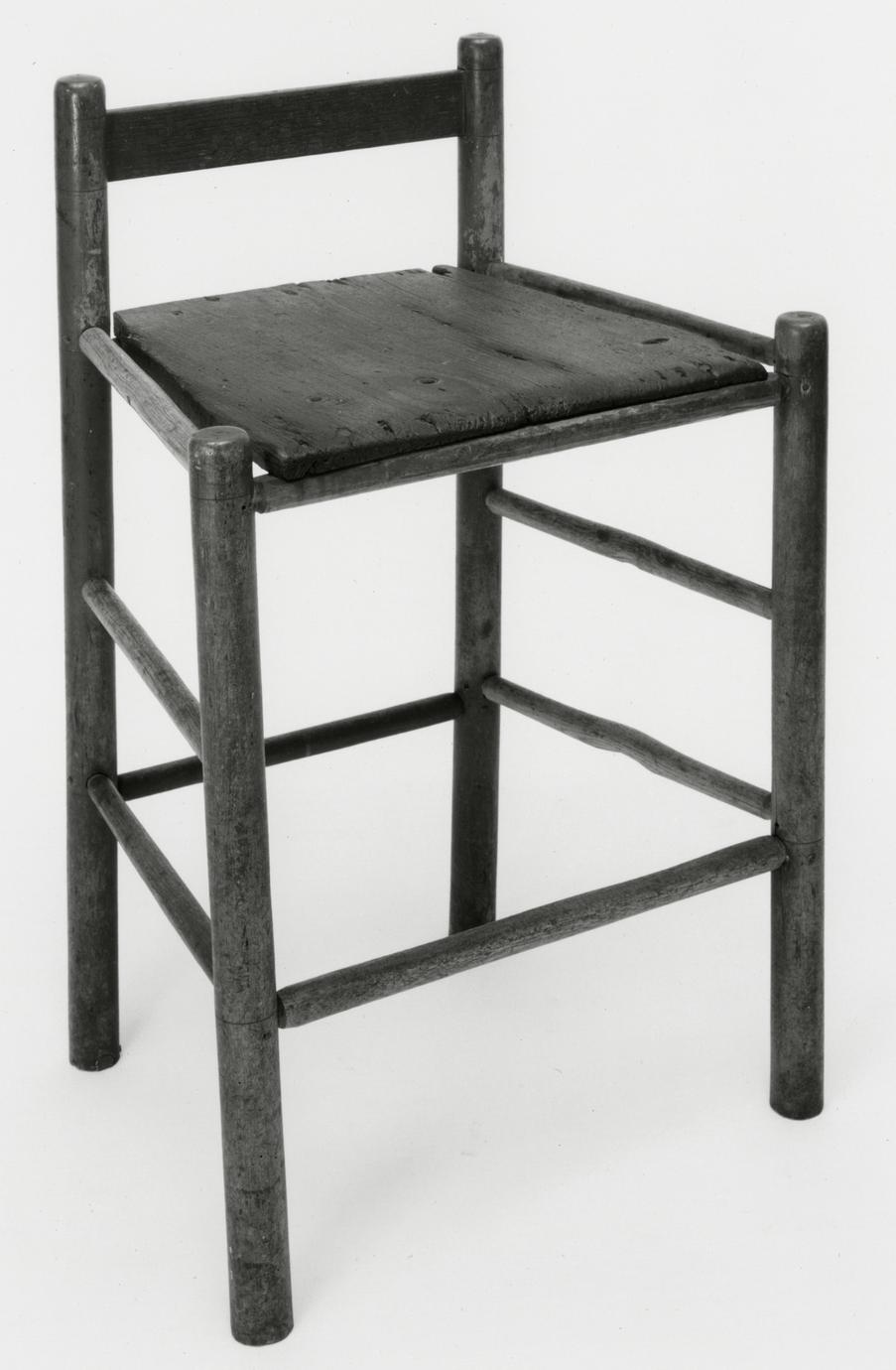
arm supports, seat rails, and stretchers. The stop
provided by the wood shank prevented a hole's
becoming more than 1¼ inches deep. A chair made
by the Dominys, and displayed in the reconstructed
woodworking shop at Winterthur Museum, has
holes measuring exactly ⅝ of an inch in diameter
and 1¼ inches in depth.
The long-shafted bit (B), made of a few pieces of
iron welded together, was used for a special purpose—in
a restricted space, for example—where the
brace would be difficult to turn if a short block and
shank were used. One other spoon bit (57.26.178)
survived in the Dominy Collection. Its block is
cherry, and it is 4⅞ inches long with a cutting
diameter of 1/16 of an inch.
During the nineteenth century the terms "gouge"
and "spoon" came to be used for these bits in
literature dealing with the history of tools. Gouge
bits were defined as an open half cylinder sharpened
at the end of the blade like a gouge. Spoon
bits were generally bent up at the end of the blade
to make a taper point.46 These distinctions for what
are basically variants of the same design have been
maintained and are useful. It should be remembered,
however, that the distinction was not made
by early craftsmen or toolmakers.
Description A: Length, 14 1/6; bit diameter,
⅝. Pear block; iron blade and shaft. B: Length,
21½; bit diameter, ⅜. Pear block; iron blade and
shaft. C: Length, 9 9/16; bit diameter, ¼. Apple
block; steel blade and shaft. D: Length, 8; bit diameter,
7/32. Hickory block; steel blade and shaft. E:
Length, 6¾; bit diameter, ⅛. Hickory block; steel
blade and shaft. All probably made or purchased
by Nathaniel Dominy V. Museum accessions:
57.26.163, 57.26.166, 57.26.164–165, 57.26.173.
p. 59
13
Countersink Bits
1790–1830 East Hampton, N.Y., and England
13 A, B, C, D
A countersink bit was used to enlarge the upper
part of a previously drilled hole so that the head of
a bolt, rivet, or screw could be sunk flush with, or
below, a wood or metal surface.
"Rose hd Countersinks" is the name applied to
the two bits, A and B, by an English tool catalogue
printed on paper watermarked 1798.47 At least three
other English catalogues of the early nineteenth
century also illustrate rose-headed countersinks.48
Mercer refers to the two examples at the right as
"plug centre bits," apparently using as his source
Charles Holzapffel's Turning and Mechanical Manipulations
published in London in 1846.49
Three other countersink bits owned by the Dominys,
in diameters of 3/16, 5/16, and ½ inch, have
survived. These bits may have been supplied by
local blacksmiths because, on separate occasions in
1788 and 1791, Nathaniel IV purchased center bits
and "Screw-Box Bits" (No. 107) from Deacon
David Talmage.50
Description A: Length, 5¾; bit diameter, ⅝.
Beech stock, steel shaft and bit. B: Length, 6; bit
diameter, ½. Tulip block; steel shaft and bit. C:
Length, 6; bit diameter, ⅜. Hickory block; steel
shaft and bit. D: Length, 5⅜; bit diameter, 5/16.
Soft-maple block; steel shaft and bit. All made or
purchased by Nathaniel Dominy V. Museum accessions:
57.26.145, 57.26.144, 57.26.158, 57.26.162.
p. 60
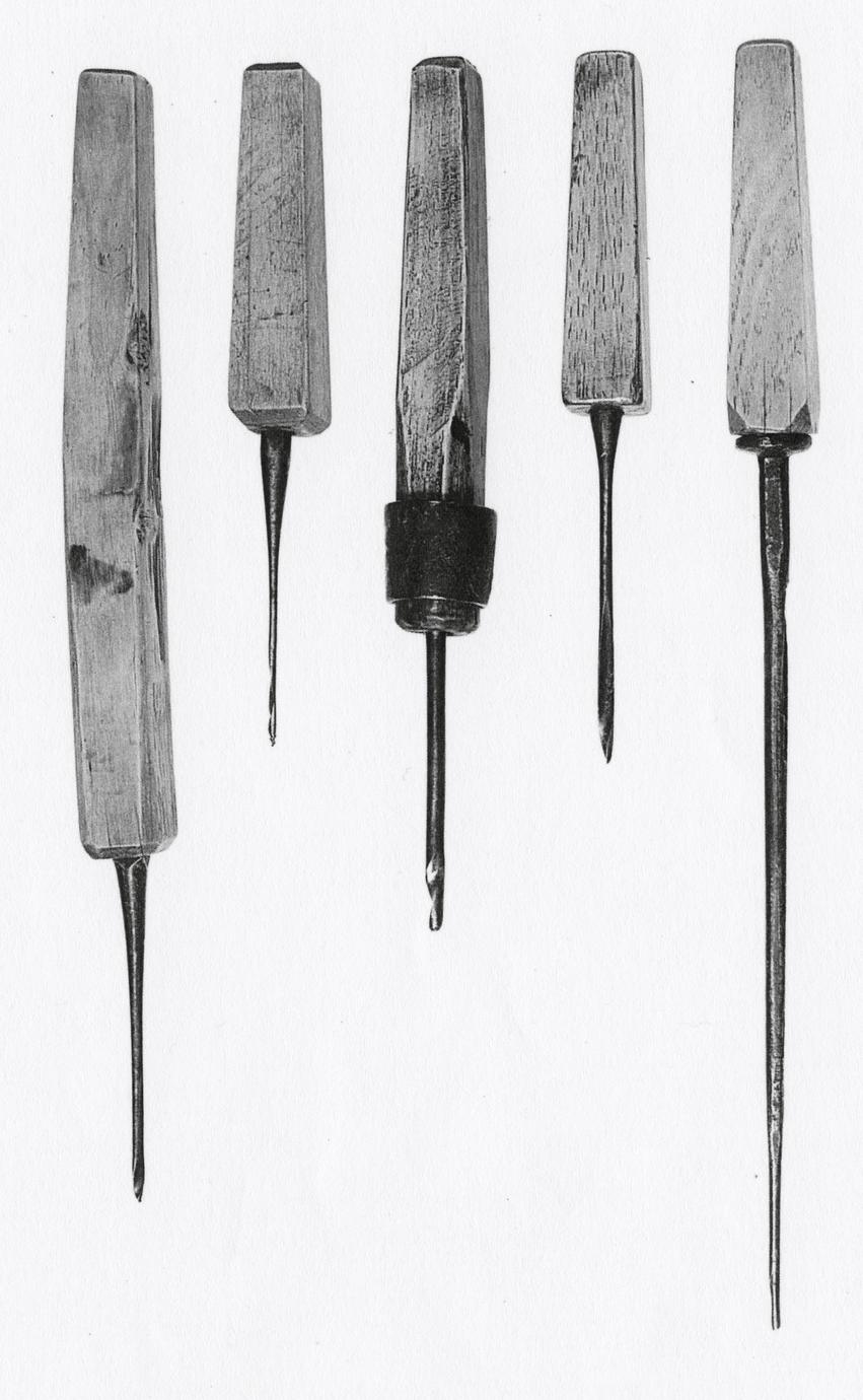
14
Gimlet Bits
1790–1830 East Hampton, N.Y., and England
14 A, B, C, D, E
According to Wildung, the gimlet bit was used to
drill pilot holes for wood screws. This is probably a
valid explanation of its use.51 Certainly the bits
shown must have been used in hardwoods (if not
metal) for, with one exception, the blades have all
broken above their starting twist.
Although the tool is referred to as a "gimlet" bit
by Mercer, its eighteenth- or nineteenth-century
name is not clear.52 The design remained consistent;
apart from hand-wrought shafts and wood
shanks, it does not differ appreciably from gimlet
bits made in 1901.53
Description A: Length, 11¾; bit diameter, ⅛.
Hickory block; steel shaft and bit. B: Length, 7 1/16;
bit diameter, 3/32. Soft-maple block; steel shaft and
bit. C: Length, 9; bit diameter, 3/16. Hickory block;
steel shaft and blade; iron ferrule. D: Length, 7 5/16;
bit diameter, 5/32. Hickory block; steel shaft and
bit. E: Length, 13 3/16,,n; bit diameter, ⅛. Hickory
block; steel shaft and bit. All probably made or
purchased by Nathaniel Dominy V. Museum accessions:
57.26.174, 57.26.176–177, 57.26.175, 57.26.172.
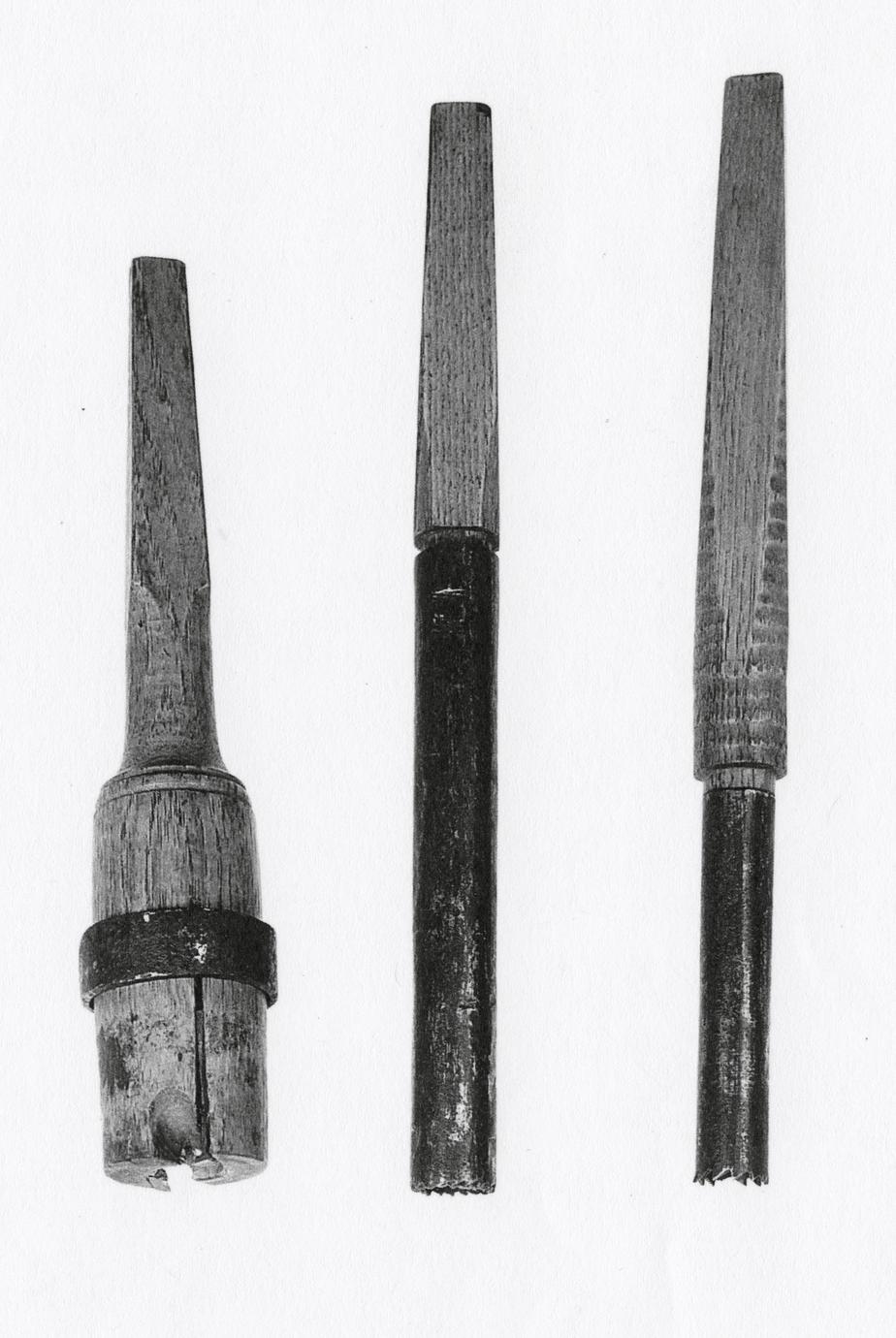
15
Nose or Wimble Bits
1790–1830 East Hampton, N.Y., and England
15 A, B, C, D, E
These hand brace bits are related to the nose, or
downcutting, auger (Nos. 2-4).54 The projecting
lip, or notched blade, seen most clearly on C and E,
allows wood shavings to accumulate in the spoon,
or hollow portion, of the bit. The shavings had to be
removed frequently from the hole cut by this tool.
Consequently, they were probably the least efficient
of all cabinetmakers' bits.
Bits of this type are shown in several contemporary
English tool catalogues. They are called "nose
bits" by Belcher and Hunter but in the Book of
Patterns they appear as "wimble bits."55 The latter
was apparently a generic term used in the eighteenth
century to denote tools used for boring holes,
such as a gimlet, auger, brace, or bit.56
Description A: Length, 13 9/16; bit diameter, ⅝.
hickory block; steel shaft and bit. B: Length, 12⅝;
bit diameter, ¼. Hickory block; steel shaft and bit.
C: Length, 12⅝; bit diameter, 7/16. Hickory block;
steel shaft and bit. D: Length, 10 7/16; bit diameter,
¼. Apple or pear block; steel shaft and bit. E:
Length, 5; bit diameter, 5/16. Hickory block; steel
shaft and bit. All probably made or purchased by
Nathaniel Dominy V. Museum accessions:
57.26.171, 57.26.170, 57.26.169, 57.26.167–168.
p. 61
16
Reamer Bits
1800–1830 East Hampton, N.Y., and England
16 A, B
In his Cabinet Dictionary Thomas Sheraton stated
that a complete set of cabinetmaker's bits amounted
to "near four dozen."57 Reamer bits would undoubtedly
have been included, and these examples
are evidence that the Dominys had use for this type
of tool. Their purpose was to widen, or ream, previously
drilled holes.
The more precise machining of the reamer blade
at the left of the illustration relates it to English
examples such as the bit shown in the Book of
Patterns. It was probably used by the Dominys on
soft metal such as brass and on hardwood. An obviously
rough, hand-wrought blade characterizes
the reamer at the right; it was probably made by a
local blacksmith.58 One other reamer bit
(57.26.194) survived in the Dominy Tool Collection;
it is similar to the bit at the right but about
one-half its length.
Description A: Length, 8 11/16; bit diameter, ¼.
Hickory block; steel blade, probably English. B:
Length, 9⅞; bit diameter, ½. Hickory block; iron
blade. Both made or purchased by Nathaniel Dominy
V. Museum accessions: 57.26.153, 57.26.152.
17
Spiral Bits
1810–1840 America
17 A, B, C, D, E
There is an obvious relationship between the spiral
bit and the spiral auger (cf. No. 5). The history of
the development of a twisted blade, providing the
advantage of boring a hole faster and straighter
while removing wood shavings at the same time, is
discussed above under the auger.
All the Dominys appreciated the efficiency of spiral
bits. Seven examples used by Nathaniel V and
his son Felix have survived. It is evident from the
number of late examples that their handymen descendants
replaced early bits with improved spiral
forms.
English tool catalogues of the late eighteenth and
early nineteenth centuries carried no illustrations
of spiral bits. This suggests that the Dominys obtained
these examples from American toolmakers.
As late as 1880 Knight noted that "twisted drills are
in much favor among American mechanics, but for
some reason are not so popular in Europe."59
Of the five examples illustrated, all but one were
twisted from a single bar of steel and probably all
had starting screws originally. The blade of D has
been broken, and it is impossible to know whether
or not it had a starter screw. It is the only one made
p. 62
from steel wire in the group and is probably the
latest in date.
Description A: Length, 8¾; bit diameter, ⅝.
Dogwood block; steel shaft and blade; copper-wire
ferrule. B: Length, 9; bit diameter, 9/16.
American-beech block; steel shaft and blade. C:
Length, 10¾; bit diameter, 7/16. Dogwood block;
steel shaft and blade. D: Length, 8 9/16; bit diameter,
¼. Hickory block; steel shaft and blade. E:
length, 5½; bit diameter, ¼. Soft-maple block;
steel shaft and blade. All probably made or purchased
by Nathaniel Dominy V. Museum accessions:
57.26.179, 57.26.186, 57.26.183, 57.26.187,
57.26.184.
18
Spiral Bits
1810–1840 America
18 A, B, C
From the number of unidentified tools in various
collections it can be deduced that craftsmen occasionally
made special-purpose tools for particular
tasks. These tenon-cutting bits are examples of the
type of implement for which no illustration or document
can be found.60
It is evident that they were used as bits because
the shanks are tapered to fit a brace. Tool A has
two metal cutters with the sharpened edges parallel
to the opening. The other bits have a number of
fine saw teeth cut into their metal shafts. All three
will cut only with a clockwise motion. The bits
illustrated, A-C, are designed to cut round wood
plugs 3¾, 4⅛, and 2½ inches long respectively.
Various suggestions have been made regarding
the purpose of these bits. Perhaps the most pertinent
is that they were used to produce the round
tenon, or dowel, at the end of stretchers, arm supports,
spindles, and other parts of chairs made by
the Dominys. The center bit (B) fits the tenon of
an arm support for a slat-back chair made by Nathaniel
Dominy V, while the lower bit (C) fits the
side-stretcher tenon of the same chair. A plug, or
dowel, only ⅜ of an inch in diameter could be cut
by A, and it may have been used for parts of chairs
made for children. That type of chair is mentioned
in the Dominys' accounts, and because its parts
were proportionally smaller it required smaller
tenons.
Description A: Length, 10; cutting edge diameter,
⅜. Hickory shaft; steel cutter. B: Length,
11 9/16; cutting edge diameter, ¾. Ash shaft; steel
cutter. C: Length, 11⅞; cutting edge diameter,
11/16. Hickory shaft; steel cutter. All made by
Nathaniel Dominy V. A, Gift of Robert M. Dominy,
1957. Museum accessions: 57.93.64, 57.26.143,
57.26.142.
p. 63
BRACES
19
Brace or Bitstock
1790–1820 England
19
A similar tool in a plate in an English catalogue has
the caption "Gentlemens Iron Braces" (see Illus.
XVII).61 Such a designation in a period when the
term "gentlemen" was seldom applied to craftsmen
is intriguing.
One side of the pad of this brace has the initials
ND stamped with a circular punch, a mark usually
identifying Nathaniel Dominy IV. However, the
similarity of this brace to one in a catalogue of the
late eighteenth century (they are almost identical),
plus its Australian blackwood or rosewood cap,
would seem to indicate that it was purchased no
earlier than 1790 and probably later. Although Nathaniel
IV lived until 1812, it is likely that the
original purchaser was his son.
A thumbscrew for securing bits in the pad is
missing. The Dominys probably did not have much
use for iron braces. An earlier example, late seventeenth
or early eighteenth century (57.26.16), also
survived in the Dominy Tool Collection. It is
Illus. XVII. "Gentlemens Iron Braces." From "Book
No 25," Book of Patterns (n.p., n.d.), p. 60.
longer (11⅞) and has a wider cap (3⅛). In his
Panorama of Science and Art Smith stated that
"stocks" were "frequently made of iron," though
"generally of wood."62 Apparently woodworkers
preferred a wooden brace with a pad that permitted
a rapid transfer of bits. Only three bits for these
braces survive, probably an indication that few
were purchased.
Description Length, 9⅞; cap diameter, 2⅝. Iron
pad and shaft, pad stamped with initials ND; Australian
blackwood or rosewood cap. Probably purchased
by Nathaniel Dominy V. Museum accession:
57.26.17.
p. 64
20
Braces or Bitstocks
1760–1802 East Hampton, N.Y., and England
20 A, B
During the eighteenth and nineteenth centuries
this useful tool was known by at least three names:
Joseph Moxon refers to it as a "Piercer"; advertisements
in colonial newspapers and authors of how-to-do-it
manuals such as Nicholson and Smith call it
a "stock"; and English tool catalogues refer to the
form as a "brace."63
The Dominys and other contemporary craftsmen
used this tool to hold various types of bits in the
manner illustrated. It operated as a crank to enable
a worker to drill holes with greater speed and continuity
than possible with a gimlet or auger.64 Steel
ferrules protect the edges of the pad where pressure
from the bit would cause a tendency to split the
wood. Heavy pressure often caused wooden braces
to split, and if one looks closely at the frame to the
left of the cap, a large break can be seen. It was
mended with a brass plate, screws, and copper rivets
on the underside. Both tools show the wear of hand
pressure and rubbing. On brace A, Nathaniel Dominy
V used a die to stamp DOMINY in a serrated
rectangle above the date 1802.
Brace B is unmarked but was probably made
earlier by Nathaniel IV. Although its design appears
similar to that of nineteenth-century brass-plated,
spring-catch wood braces made in England
in large quantities, it is actually close to the design
of a brace dated by R. A. Salaman as mid-eighteenth
century.65 Its ferrule (one is missing) is
made of iron, rather than steel. Although only 1⅝
inches longer than the 1802 example, its wood
frame is thicker and heavier. In making this brace
Nathaniel IV used a typical craftsman's device of
the eighteenth century: nonessential surface was
discarded for both a useful and a decorative or
aesthetic effect. Thus the deep chamfering of its
edges heightens the effect of its curved surface without
compromising the tool's strength, producing an
object that is utilitarian and beautiful.
Three other wood braces (57.26.19, 57.26.21,
60.354.2) used by the Dominys have survived. Two
of these are of the English brass-plated, spring-catch
type seen in English tool catalogues and illustrated
recently by Wildung.66 One of these braces
(57.26.19) is stamped MOULSON and was made in
Sheffield by the Moulson Brothers between 1828
and 1841.67 Although it is generally thought that
braces strengthened by the addition of metal parts
p. 65
were introduced in the nineteenth century, they
were actually in use during the last decades of the
eighteenth century. The Annapolis, Maryland, cabinetmakers,
Shaw and Chisholm, advertised in
1773 that they had imported "Neat brass mounted
stocks with 36 bits for each."68
Description A: Brace length, 13¼; cap diameter,
2 5/16; bit length, 8; blade diameter, 7/32. Beech
stock stamped DOMINY in serrated rectangle and
1802; hickory cap; steel ferrule; apple bit head;
steel blade and shaft, probably English. B: Brace
length, 14⅞; cap diameter, 2½; bit length, 9 9/16;
blade diameter, ¼. American-beech stock; American
soft-maple cap; iron ferrule; apple bit head;
steel blade and shaft, probably English. A made by
Nathaniel Dominy V. B made by Nathaniel Dominy
IV. Bits probably purchased by Nathaniel Dominy
V (see No. 12). Museum accessions: 57.26.18,
57.26.165, 57.26.20, 57.26.164.
BURNISHER AND SCRAPER
21
1800–1830 East Hampton, N.Y.
21 A (top), B
Burnishers and scrapers were inseparable tools because,
like the brace and bit, they worked together
in woodworking. By grasping the handles of the
burnisher and pushing its steel rod over the scraper's
blade, a razor-sharp burr on either side of the blade
could be produced. The scraper was especially useful
to cabinetmakers in finishing the surface of
mahogany or other curled or cross-grained hardwood.
As explained by James Smith in 1815 or
1816, the penultimate process in preparing hardwood
surfaces employed a "tooth-plane," with a
blade set in a stock in order to present an almost
perpendicular edge of fine teeth to the wood:
"With this kind of plane, however hard the stuff
may be, or however cross and twisted its grain, the
surface may be made every-where alike, and will
not be rougher than if it had been rubbed with a
piece of new fish-skin. This roughness may be effectually
removed with the scraper, which is a thin
plate of steel, like part of a common case-knife, the
back of it being let into a piece of wood, as a
handle."69
Mercer states that craftsmen of the early nineteenth
century made scrapers from broken saw
blades, citing as evidence a reference in J. Stokes's
Complete Cabinetmakers' and Upholsterers'
Guide.70 Although scrapers of the type illustrated
here were manufactured in quantity in England,71
there are many reasons to believe that this scraper
and its burnisher were made by Nathaniel Dominy
V. The scraper's cutter was originally a saw blade,
and its soft-maple handle is stamped in a
serrated rectangle (see No. 31).
Smith's reference to the use of fishskin as an
agent for rubbing the surface of wood is an interesting
confirmation of other late-eighteenth- and
early-nineteenth-century references. Sandpaper is
not mentioned in Dominy accounts until 1815,
when Nathaniel V credited Abraham Hedges with 6
pence for a supply of it.72
Description A: Length, 3⅛. Soft-maple block
stamped DOMINY in serrated rectangle; steel
blade. B: Length, 10 3/16. Soft-maple handles; steel
rod. Made by Nathaniel Dominy V. Museum accessions:
57.26.206, 57.26.121.
p. 66
CALIPER
22
1750–1800 England
22
This tool was constantly used by wood turners to
check the diameter or thickness of stock being
turned on a lathe. The example illustrated could
very well date between 1750 and 1775. The cyma
and reverse-cyma curve and incised line decoration
typify the efforts of eighteenth-century toolmakers
to beautify their products. The half-round lower
sections of the arms have obviously been wrought
from rectangular bar stock visible on the upper
part of each arm. Note, too, that the contact surfaces
of the arms are smooth and broad, enabling
them to ride on the surface of turning wood without
scoring or tearing.
The design of this caliper most resembles one
illustrated as Plate 10, Figure 2, in Hulot's L'art du
tourneur mécanicien (Paris, 1775). The author describes
it as "un compas d'épaisseur simple" (a
simple compass for measuring thickness). The fact
that the Dominys' example does not resemble calipers
illustrated in Salivet, Diderot, Mercer, or English
tool catalogues may support the belief that it
was made during the second quarter of the eighteenth
century.73 The initials AK are stamped on
one arm of this caliper, but they have not been
identified.
Description Length, 4 11/16; width (closed),
1⅛. Steel arms stamped AK; iron rivet. Probably
purchased by Nathaniel Dominy IV. Museum accession:
57.26.44.
CANT HOOK
23
1800–1830 America, Probably East Hampton, N.Y.
23
The Dominy accounts contain several references to
customers who paid debts with walnut, sassafras,
cherry, or "appletree" logs. Because logs had to be
felled, moved, and shaped for milling, a cant hook
was necessary for the moving operation. It is not
surprising to find that the Dominys owned one. By
setting the wrought-iron hook (which swings
loosely in a mortise) in a log and applying pressure
to the handle, they could roll a log in whatever
direction was desired. This example is unlike the
group shown in Mercer, and no cant hook is pictured
in eighteenth- or early-nineteenth-century
sources.74
According to the Oxford English Dictionary, the
earliest use of the term "cant hook" occurred in
America in 1848. An 1833 view of the Smith and
Dimon Shipyard in New York City, painted by
John Pringle, shows four workmen with cant hooks
near a huge log being cut by two laborers with a
whip (crosscut) saw.75 The shapes of their cant
hooks are quite similar to that of the Dominys.
Description Length, 50½; hook length, 11½;
shaft width, 2¼; hook width, 1⅜. White-oak shaft;
iron rivet, hook, and washer. Made or purchased by
Nathaniel Dominy IV or Nathaniel Dominy V.
Museum accession: 57.26.260.
p. 67
CHISELS
24
Mortising, Firming, and Paring Chisels
1790–1850 East Hampton, N.Y., and England
24 A, B, C, D, E, F, G, H, I, J, K
These eleven chisels are a majority of the seventeen
that survive in the Dominy Tool Collection. Split
and broken handles are evidence of their abuse by
later generations of Dominys who probably used
hammers instead of mallets to strike the handle
ends. That abuse resulted in short lifetimes for
many Dominy chisels when coupled with natural
attrition; most eighteenth-century chisel blades
were formed of a thin layer of steel heat-welded to
iron, and the layer frequently had to be replaced.
These factors probably account for the preponderance
of early-nineteenth-century chisels in the collection.
By that time only large or inexpensive chisels
were made of steel and iron.76 For example, the
only cast steel used in the large socket-firmer chisel
(K) is on the cutting edge and cutting face, as is
clearly shown by the split, or division, just above
the edge.
Mortise chisels (A-C) cut rectangular holes into
which tenons were fitted, as where a rail might join
the top part of a leg on a case piece of furniture or
chair. In some instances (for example, the cant
hook shown in No. 23), the mortise hole was
merely a receptacle for some moving part. The
shape of its blade enabled fairly straight, deep incisions
to be made in softwoods and in hardwoods
previously bored.77 Chisels of this type were generally
ordered eight to a set (see Richard John's
order, Chapter III). The catalogue issued by Cutler
and Company, Sheffield (1833–1837), states that
both joiners' and cabinetmakers' sets were provided
in that number. Their chisels were made in thirteen
sizes ranging from 1/16 of an inch to 1 inch.78 It
p. 68
is clear that, with thirteen sizes available in sets of
eight, there was bound to be some overlap in sizes
used by joiners and cabinetmakers.
The Dominys owned at least seven mortise chisels.
Of the four not illustrated (57.26.62, 57.26.63,
57.26.65, 57.26.237), two had blades stamped W.
BUTCHER, a mark used by the Sheffield firm of
William Butcher from 1818 to 1828.79 The mark
also appears on a firmer chisel (I).
Of the remaining chisels, five are firmer and
socket types, while three might possibly qualify as
paring chisels. The firmer, or forming chisel, was
the first chisel used by woodworkers in cutting away
superfluous wood. Called a "Former" by Moxon
because it was used first, it is referred to in later
sources as a "firmer." English tool catalogues do not
illustrate paring chisels. No distinction was made
between types except to note whether power was
supplied by a mallet or by hand and shoulder. If
struck with a mallet, the chisel was a firmer; if
pushed by hand, it was a paring chisel.80 A firmer
not illustrated (57.26.252) was made or sold by the
firm of John Tillotson, Sheffield.
A chisel with a blade stamped WELDON (D)
and its companion (E) started life as firmers but
were converted by the Dominys for a special purpose.
They may have been used for carving gunstocks
or for finishing fluted decoration on cabinetwork.
Their rounded shoulders would not be prone
to tear the edges of a channel. WELDON was a
mark used on tools from 1787 to 1841 by four
Sheffield firms: William Weldon; Weldon and Furniss;
Furniss, Cutler and Stacey; and Cutler and
Company. A cast-steel fluting chisel (63.156.194)
made in Sheffield sometime between 1817 and 1833
is not shown.81
Next to these chisels is an example (F) of a blade
converted from a file. Its cutting edge is both
skewed and curved. The absence of wear from
being struck by a mallet and the further absence of
indentations from strain against the tool rest of a
lathe indicate that this chisel was used for paring.
Socket chisels (J, K) were heavy-duty firming
and mortising chisels useful to the carpenter rather
than the cabinetmaker. These were efficient in preparing
mortise holes for beams in houses and mills.
The stamp W. L. JONES has not been identified,
but WILCOX & CO. was probably a mark used by
A. Wilcox & Co., manufacturers of edge tools in
Rocky Hill, Connecticut, in 1849.82 This is the latest
chisel in the group illustrated and was undoubtedly
purchased by Nathaniel Dominy VII.
Description A: Length, 10¾; blade width, 1 1/16.
Hickory handle; steel blade and ferrule. B: Length,
9 3/16; blade width, ¼. Birch handle; rough-forged
steel blade, possibly East Hampton, New York. C:
Length, 6½; blade width, ⅛. Hickory handle; iron
blade with steel face. D: Length, 8⅞; blade width,
⅝. Ash handle; steel blade stamped WELDON
(Sheffield, England, 1787–1841). E: Length, 9 5/16;
blade width ½. Hickory handle; steel blade. F:
Length, 7¾,; blade width, ⅜. Soft-maple handle;
steel converted-file blade; iron ferrule. G: Length,
6; blade width, 5/16. Hickory handle; steel blade. H:
Length, 10¾; blade width, 1. Beech handle; iron
blade. I: Length, 11⅛; blade width, 1¼. Dogwood
handle; cast-steel blade stamped W. BUTCHER /
CAST STEEL (Sheffield, England, 1818–1828). J:
Length, 13 3/16; blade width, 2. Hickory handle;
iron blade with steel face stamped W. L. JONES.
K: Length, 17 5/16; blade width, 1⅞. Hickory handle;
iron blade with cast-steel face stamped with an
eagle and WILCOX & CO / CAST STEEL /
WARRANTED (Rocky Hill, Connecticut, ca.
1849); steel ferrule. All made or purchased by
Nathaniel Dominy V and Nathaniel Dominy VII.
Museum accessions: 57.26.66, 57.26.64, 63.156.54,
57.26.67–68, 63.156.144, 63.156.103, 57.26.118,
57.81.25, 57.26.250, 57.26.115.
25
Turning Chisels
1750–1830 East Hampton, N.Y., and England
25 A, B, C, D, E, F, G
With two lathes (Nos. 48, 49) in the Dominy woodworking
shop, it is to be assumed that considerable
time was spent in turning wood, bone, and metal
objects. The number of turned chairs and stands
illustrated in Chapter VI are proof of the Dominys'
skill in wood turning. Turning chisels were vital in
lathe work and were utilized after initial rough
shaping by a gouge (No. 41). As Moxon and succeeding
authors put it, flat chisels (A, C, and E)
"do the Office of Smoothing plains in Joyning and
Carpentry."83 They smoothed irregularities left by
the gouge and reduced the whirling surface of the
stock to a uniform size.
Tool E is, perhaps, one of the most handsome of
the turning chisels. Nathaniel III or IV converted it
from the fine steel of a seventeenth-century sword
or dagger blade. A flower-and-leaf design and the
date 1660 are inlaid in brass. On the opposite side
are inlaid the word ANNO and a bird design. Visible
p. 69
on the handle of C are Felix Dominy's initials,
indicating that he used it and might have made the
handle for it. The turning chisel at the far right
(G) shows the conversion of a worn file to a useful
tool. A blade with a similar shape is illustrated as
Figure 7 in Plate XIX of Salivet's Manuel du tourneur
(Paris, 1792) and is described as a "half-round
chisel" for "hollowing or digging" half-round moldings."84
This turning tool would have been especially
useful in shaping the edges of circular-top
candlestands made in quantity by the Dominys
(Nos. 247–50, 254, 255). It is also a good example
of the danger involved in dating a tool by one
design element. The blade is stamped with the initials
BN under a stylized crown, a mark used by
Samuel Genn, a filesmith, of Sheffield, from 1774 to
1787.85 Its handle, however, is stamped with the
initials FD, used by Felix Dominy when he converted
the file to a chisel in the early nineteenth
century.
A thin-bladed chisel with rough-hewn handle
(F) may have been used as a "diamond-point"
chisel for turning brass. It is difficult to make a flat
statement about this kind of turning tool because
p. 70
these "point" chisels were often used to turn hardwood,
ivory, and metals.86 The Dominys turned all
three materials and this chisel was therefore probably
used on each. A worn surface on the blade
shank just below the handle indicates that the
chisel was used with the beveled edge pointing
down and away from the user.
There is little doubt that the blunt-edged chisel
(D) was used in turning metal such as brass, rather
than in working on wood surfaces. Perhaps it is the
"3 square Turning Chizzel" that David Talmage,
Jr., made for Nathaniel Dominy IV in 1795 at a cost
of 3 shillings.87 Certainly no better description is
available for the shape of the blade. Both Nicholson
and Smith state that triangular and square-edged
turning tools were designed for use on brass,
iron, and steel. Knight, however, mentions that
square-edged turning chisels were sometimes used
in smoothing wood.88 On at least one occasion Nathaniel
IV turned "hand iron heads" (andiron
heads) for William Hedges, and a turning tool of
this type would have been most useful in that kind
of operation.89
One other turning chisel (57.26.78) has survived,
but because of its broken blade it is not illustrated.
With steel shaft and plain, octagonal, soft-maple
handle, it was probably made during the early nineteenth
century.
Description A: Length, 19¼; blade width, 1.
Soft-maple handle; horn ferrule; iron blade with
steel face. B: Length, 19 3/16; blade width, 7/16.
American hickory handle; horn ferrule; iron blade
with steel face. C: Length, 17¾; blade width, 1½.
Soft-maple handle stamped FD; horn ferrule; iron
blade with steel face. D: Length, 16⅛; blade width,
¾. Hickory handle; horn ferrule; iron blade. E:
Length, 14¼; blade width, ½. Soft-maple handle;
horn ferrule; steel blade inlaid with brass. F:
Length, 13⅝; blade width, 5/16. Hickory handle;
iron blade with steel face. G: Length, 13; blade
width, 1. Ash handle stamped FD; iron ferrule;
steel blade stamped BN under stylized crown, mark
of Samuel Genn, Sheffield, 1774–1787. A and B
made or purchased by Nathaniel Dominy V. C, F,
and G made or purchased by Felix Dominy. D and
E made or purchased by Nathaniel Dominy IV.
Museum accessions: 57.26.71, 57.26.70, 57.26.69,
57.26.413, 57.26.119, 57.26.285, 57.26.122.
CLAMPS
26
Clamps
1790–1830 East Hampton, N.Y.
Clamps are commonly used to bind glued surfaces
tightly together until the fastening material has set.
Clamps, incidentally, do not appear in eighteenth-
or early-nineteenth-century tool catalogues, nor
were they offered for sale in the advertisements of
tool distributors that appeared in American newspapers
of the same period. It can be reasonably
assumed that these wood clamps were made and
used in the Dominy woodworking shop. American
wood was used in their construction; and the presence
of conjoined initials ND on C plus the name
DOMINY struck on the end of both blocks of A
suggests their East Hampton origin.
Only one contemporary reference can be found
that relates to the use of a clamp, and it refers to
the type shown as Figures 18 and 19 in a plate from
Roubo (Illus. XVIII).90 Lacking illustrations of
eighteenth- or nineteenth-century examples, it is
difficult to know exactly when the clamps shown
here were made. From the standpoint of design, the
earliest example is probably A and the latest example,
B. The latter is closest in design to
nineteenth-century clamps illustrated in Mercer's
book.91 The screws for all these clamps were probably
made in the screw box shown as Number 107.
That tool was being used in the Dominy shop by
1791, because in August of that year Nathaniel
Dominy IV credited Deacon David Talmage for
5 shillings 8 pence for "Screw-Box Bits &c."92
Four other clamps of the type illustrated, with
blocks ranging from 13⅛ to 20⅛ inches, have survived
(57.26.218–221). Of these, one pair of clamps
(57.26.219) has the initials ND scratched on its
surface.
Description A: Length, 8¾; depth, 1 11/16.
Red-oak arms stamped DOMINY; ash screws. Gift
of Robert M. Dominy, 1957. B: Length, 13⅞;
depth, 2⅛. Unidentified arms; dogwood screws with
hickory head; birch screw block. C: Length, 13 7/16;
depth, 2 5/16. Red-oak arms stamped ND; hickory
screws. All made by Nathaniel Dominy IV and
Nathaniel Dominy V. Museum accessions: 57.93.60,
57.26.608–609.
p. 71
26 A (top), B, C
p. 72Illus. XVIII. Tools suited to the joining and gluing of wood. From André Jacob Roubo, L'art du menuisier
(Paris, 1769–1775), III, Plate 18.
p. 73
27
Panel Clamp
1760–1800 East Hampton, N.Y.
27
Active woodworkers like the Dominys needed large
clamps that would hold together the frame and
panels of house doors, interior wall paneling, or the
paneled doors of a desk and bookcase. The clamp
shown was their solution to the problem involved
in tightly seating mortise-and-tenon joints in order
to hammer pegs into them.
It is possible that this craftsman's solution was
original. Panel clamps shown in Mercer have screw
pressure exerted on movable pegs, or tenons, while
here the force is pressed against a block-and-ratchet
design. A bold, hand-wrought ram's-horn nut and
an iron screw fasten the block in place. The closest
form in contemporary literature is a clamp illustrated
by Roubo (Illus. XVIII).93 Its ratchet design
could be an indication of a common eighteenth-century
practice, but in the absence of other examples
the Dominys' clamp provides a unique survival.
A smaller clamp (57.26.222), perhaps used for
the same purpose, also survives. It is only 33½
inches long, with a fixed block at the front and a
movable block and screw at the opposite end.
Description Length, 62; height, 6; depth, 2⅜.
Fixed and movable block, shaft, white-pine; hickory
screw; iron ram's-horn nut, screw, and washer.
Probably made by Nathaniel Dominy IV. Museum
accession: 57.26.226.
28
Slat-bending Clamp
1800–1840 East Hampton, N.Y.
28
The Dominy craftsmen made chairs in great quantities,
and this clamp was used to force slats for
chairs to retain a curved shape (see Nos. 182, 189).
After the wood slats were steamed over boiling
water or actually dipped in hot water, they became
flexible and could be bent. By pushing one end of
the slats against an upright block of the clamp and
then putting the other movable block in place, the
slats, when dried, conformed to the curved shape of
the clamp. The thickness of slats used in chairs
made by the Dominys indicates that this clamp
would hold four slats.
This type of clamp is not described in any literature
pertaining to craft techniques or tools. Perhaps
it was an original solution to a problem encountered
by the Dominys.
Description Length, 27 1/16; height, 7½; depth,
3⅞. Tulip moving blocks; white-pine templates;
red-oak center shaft. Made by Nathaniel Dominy V.
Museum accession: 57.26.223.
p. 74
COMPASSES
29
Cooper's Compass or Divider
1770–1830 Probably England
29
Because this tool is a compass capable of adjustment
to a fixed position, it qualifies as a divider.94
In eighteenth- and early-nineteenth-century sources,
however, it is described merely as "a compass," albeit
a special type used by coopers.
When a barrel or cask was completed, the cooper
used the points of this compass as an inside caliper
top. With the measurement fixed, he scribed a
circle of the same diameter across a group of
boards. When this circular pattern was cut and the
boards fastened together, a tight-fitting head was
produced. Diderot illustrates a compass of this type
in describing the activities of the cooper ("tonnelier")
and calls it a "compas à quart de cercle," no
doubt because the arm will adjust over a one-quarter
arc of a circle.95
While this type of compass was designed for use
by coopers (for example, Roubo illustrates the
usual type for cabinetmakers, without an adjusting
arm, on Plate 15 of his work), the Dominys probably
used it in other endeavors. It would have been
useful, for example, in scribing circular patterns for
the small circumferences of woolen wheels or Dutch
wheels. English tool catalogues list these compasses
in several sizes, but one, Book of Patterns, with
paper watermarked 1798, offers them with a reach
up to 18 inches. This example will open to 18½
inches. Around 1800 the wholesale cost of this instrument
was 50 shillings per dozen, or 4 shillings 2
pence apiece. Because the Dominys valued a day's
labor at about 7 shillings, a compass of this type
would have cost more than a half day's pay.
At first it seemed possible that this tool might be
placed in the third quarter of the eighteenth century.
The heart-shaped thumbscrew, hand-hammered
chamfered edges, and small volutes at
the top of the arms appear consistent with eighteenth-century
tool design. The fact that this type of
thumbscrew and chamfering is shown in early-nineteenth-century
tool catalogues, coupled with
the fact that a maker's name, S. JARVIS (unidentified),
is stamped on the arc in a style introduced
in the late eighteenth century, accounts for the
cautious date, 1770–1830, assigned above.
Description Length, 12⅞; width (closed), 1½;
width (open), 18½. Iron compass stamped S. JARVIS.
Probably purchased by Nathaniel Dominy IV.
Gift of Nathaniel M. Dominy, 1960. Museum accession:
60.354.1.
30
Compass or Oval-tracing Machine
1760–1800 East Hampton, N.Y.
30
At first glance, this compass would appear to be a
clockmaker's beam, or rod, compass used to scribe
large circles for clock dials.96 It was used by cabinetmakers
and turners, however, to trace ovals.
This kind of tool is illustrated in Roubo's treatise
on woodworking, in a plate headed "Machine
propre a tracer les ovals." In his text the author
describes it as a "Croix ou equerre mobile" (cross
mark or moving square) and states that it was used
to cut out ("découper") ovals.97 The same compass
is shown by Salivet in 1816, who described it as a
"tool for tracing ovals."98
Only the compass itself survived in the Dominy
Tool Collection; its cross, or track, is a modern
replacement made by the Winterthur Museum's
cabinetmaker. The length and width of the oval to
be scribed is determined by adjustment of the two
blocks seated in the track. Loosening each of their
p. 75
wedges permits them to move along the rectangular
bar. Thin rectangular pieces of ivory are attached
to the bottom of the blocks, enabling them to glide
smoothly in the tracks. The compass point is a piece
of iron sunk into a block. A turned handgrip enables
the user to guide the compass and exert pressure
on the surface of a board.
At least three oval tables were made in the Dominy
shop. In 1766 Nathaniel IV billed Henry Conkling
£1 4s. for such a table, and on September 14,
1792, Nathaniel V made one for his uncle John
Dominy at a cost of £1 16s.99
Description Length, 39 3/16; height, 4⅝; depth,
1½. Birch shaft; American soft-maple sliding
blocks; satinwood wedges; modern cross (replacement).
Probably made by Nathaniel Dominy IV.
Museum purchase from Robert M. Dominy, 1957.
Museum accession: 57.93.49.
DIES
31
Initial and Name Dies
1760–1820 America, Probably New York
31 A, B, C
In 1732 a South Carolina craftsman, James Rousham,
advertised the loss of some of his tools. In his
notice he mentioned that a saw handle was marked
with the initial R, presumably his own.100 Recently,
when the tools of Samuel Wing—a cabinetmaker of
Sandwich, Massachusetts, and a contemporary of
the Dominys—were recovered by staff members of
Old Sturbridge Village, many were stamped with
the original owner's name, S. WING. It was common
for craftsmen to stamp tools with initials or
name as proof of ownership, and the Dominys were
no exception to this practice.
Their initials and names have survived not only
on the tools in the collection, but fortunately on
some of the dies used to mark their tools. No record
survives to show whether they made or purchased
the dies. Each has a steel face into which the letters
were cut. The dies used by Nathaniel IV and Felix
Dominy have raised letters; the one used by Nathaniel
V has incised letters. On the latter example
the serrated, or saw-toothed, edge of a rectangle enclosing
the name can be clearly seen.
Description A: Shaft length, 1⅞; face width, 3/16.
Iron and steel die. B: Shaft length, 3¾; face width,
11/16. Iron and steel die. C: Shaft length, 2¼; face
width, ¼. Iron and steel die. A made or purchased
by Nathaniel Dominy IV. B made or purchased by
Nathaniel Dominy V. C made or purchased by
Felix Dominy. Museum accessions: 57.26.253,
57.26.256, 57.26.254.
p. 76
32
Letter and Number Dies, with Holding Blocks
1770–1800 America, Probably New York
32 A (top), B
Diemaking was a highly skilled occupation. English
tool catalogues did not offer them for sale and
American craftsmen apparently ordered them from
local metalworkers. The Dominy accounts do not
provide any clue to the origin of these examples,
but the holding blocks were undoubtedly made in
their woodworking shop. In the Dominy shops
these dies were primarily used to mark tools and
clock parts. At the lower right-hand corner of the
upper block can be seen the reversed, conjoined
initials ND, indicating where Nathaniel IV's die
(No. 31) was originally held.
It is obvious from the unfilled holes in the blocks
that many of the letter and number dies used by the
Dominys have not survived. Nevertheless, it is fortunate
that so many late-eighteenth-century examples
survived and can be illustrated here. Frequently
individual dies were used in combination
to produce special number or letter effects.
Description A: Block length, 5; depth, 2; height,
1¼. White-pine block; steel dies. B: Block length,
9⅞; depth, 1 5/ 8; height, 1⅜. Ceylon satinwood
block; steel dies. Letter and number face widths:
letter N, 5/32; No. 3, ⅛; No. 2, 5/32; letter h, ⅛; No.
3, 3/32; lunette, ¼; No. 1, 5/32; lunette, 1/16; Roman
numeral VI, ⅛; letter or No. 0, ⅛; letter N, 5/32;
letter J, ⅛; letter y, 3/32; No. 2, ⅛; lunette, 3/32;
letter or No. 0, 1/16; letter M, ⅛; letter P, ⅛; letter
C, 5/32; letter Y, ⅛; letter or No. 0, 1 1/6; No. 4, 3/16;
Roman numeral II, ⅛. Probably made or purchased
by Nathaniel Dominy IV. Museum accessions:
block and dies, 57.26.479, 57.26.480; dies
only, 63.156.282.
FILES
33
Files, Woodworking and Metalworking
1800–1860 East Hampton, N.Y., and England
The seven files shown present a cross section of the
thirty-two files that have survived in the Dominy
workshops. The relatively large number of survivals
is somewhat surprising since files are not usually
considered an important part of an eighteenth-century
woodworker's shop inventory. It must be
noted, however, that the Dominys were also metalworkers,
a craft in which files play a vital part. It
p. 77
33 A, B, C, D, E, F, G
p. 78
should also be noted that certain types of files,
particularly those used as tool sharpeners, were
found in cabinetmakers' and carpenters' shops in
great quantities, and Roubo confirms that float and
flat files were used by cabinetmakers for working
hardwoods.101
The thirty-two files in the Dominy Collection do
not include tool blades converted from worn files, a
fact that helps explain the preponderance of
early-nineteenth-century examples among the survivals.102
For contrast, both metalworking and woodworking
files are included in the illustration here
and in the one in the catalogue section devoted to
metalworking tools (No. 140). A, C, and E were
used on metal in the clock shop, while B, D, F, and
G were used in woodworking.
According to a foremost mid-nineteenth-century
authority on file function, type, and manufacture,
distinguishing features of these tools lay in the
shape, type, size of the teeth, and use.103 Classifications
were two: flats and floats.
Flat files were general-purpose tools used essentially
in metalwork, although Roubo shows that
such files were also used in working hardwood surfaces.
Tool B is a true file in that its teeth were
double-cut by hand, and the fineness of its teeth was
originally middle or second cut.104
Float files were of single cut, the cut having been
produced by a series of chisel blows on the original
blanks. Floats were used on both wood and soft
materials. The types and uses of these Dominy files
are as follows:
A: A flat file that was used in metalworking and
obviously employed by the Dominys in the clock
shop. It still contains an abundance of brass partides
pressed between its single-cut teeth, indicating
that it was used as a float.
B: A flat, general-purpose file (entering file),
also used in the metalworking shop.
C: A float file, designated as an oval, or crossing,
float. The tool was used for filing the crosses, or
arms, of clock gears in the Dominy clock shop.
D: A float file of coarse-grade teeth. This tool
was fashioned from another file which contained
teeth of a much finer consistency. While its shape is
similar to a file known as a "horse float," it is
almost identical to a file shown by Roubo that was
utilized in working hardwood.
E: This is a flat file used by Felix Dominy for
repairing, rather than making, watches and for
working clock pinions. Its double-cut teeth are a
smooth grade. The name Fenn and the numeral 6,
denoting size, are stamped on its tang. According to
Abraham Rees, the principal firm in London dealing
in "clock tools, engines, and rough materials
ready prepared" was "Fenn's in Newgate Street,
No. 105."105 On page 169 of Pigot and Co's City of
Dublin and Hibernian Provincial Directory (London,
1824) is a listing for Samuel Fenn, 105
Newgate Street, London, "toolmaker and dealer,"
and the same directory for 1826 and 1827 lists a
Joseph Fenn at that address.106
F: A flat file, strikingly similar to a file shown in
Cutler and Company's catalogue (ca. 1833–1837) as
a "cabinet" file. Usually, however, this type of file is
called a "half-round," or "flat-round," file. In the
Cyclopaedia of Useful Arts, Mechanical and Chemical,
Manufactures, Mining, and Engineering
Charles Tomlinson states that this kind of file was
used for hollow work and as an all-purpose file.
G: A flat file, described in Joseph Smith's tool
catalogue of 1816 as a "handsaw" file, used for
sharpening the teeth of saw blades. Its nature suggests
its usefulness in a woodworking shop.
The handles of the files tell still another story
bearing on frequency of use. Since a tool in reasonably
constant use would be found atop a workbench
or table, handles of such tools were carved to
prevent them from rolling off. Thus B and D, with
octagonal handles to prevent rolling, and C and E,
which have been shaved on two sides, would appear
to be the most frequently used of the Dominy files
shown here.
Description A: Length, 15⅝; blade width, 15/16.
Soft-maple handle; steel blade stamped CAST
STEEL / SW / WING (Sheffield, 1821–1841). B:
Length, 13½; blade width, ⅞. White-ash handle;
steel blade stamped WARRANTED / CAST
STEEL / ASHTON & JACKSON (Sheffield,
1838–1861). C: Length, 12½; blade width, ¾.
Soft-maple handle; steel blade stamped D. D:
Length, 9½; blade width, 3/16. Soft-maple handle;
steel blade stamped CAST STEEL. E: Length,
7 11/16; blade width, ⅜. American cherry handle;
steel blade stamped FENN / 6 (London, ca. 1824).
F: Length, 5¾; blade width, ⅝. Steel blade
stamped IK / KENYON (Sheffield, 1774–1841). G:
Length, 4⅝; blade width, 7/16. Steel blade stamped
CAST STEEL / W. GREAVES / & SONS SHEAF
WORKS (Sheffield, 1828–1841). A and E acquired
by Felix Dominy. B, D, and G acquired by Nathaniel
Dominy V. C and F acquired by Nathaniel
Dominy IV. Museum accessions: 57.26.530,
57.26.529, 57.26.294, 57.26.555, 57.26.539,
63.156.209, 63.156.236.
p. 79
GAUGES
34
Gauge
1804–1806 East Hampton, N.Y.
34
Large quantities of turned woodwork were produced
on the two lathes in the Dominy shop. To
measure the accuracy of the turning and to insure
some degree of uniformity for similar wood products,
these craftsmen made gauges. Fortunately this
example was marked by Nathaniel Dominy, and its
ink inscription tells us that is was used on Hook
Mill Rounds.
As related in Chapter V, one means of earning a
living for Nathaniel IV and V was mill carpentry.
Windmills require many cogs and rounds for the
gear wheels which transferred power at different
areas in the mill. Twenty-two additional gauges of
this type, ranging from 4 to 12½ inches in length,
have survived. They were used for various types of
turned work, and inscriptions indicate that at least
two of them were used for "Pump Box" measurements
(57.26.343) and "W.W. Spokes" (57.26.351).
The latter abbreviation probably meant "woolen
wheel spokes."
Description Length, 11¼; width (largest opening),
2⅞; depth, ⅝. Birch gauge inscribed in ink
Hook Mill Rounds. Made by Nathaniel Dominy V
during construction of Hook Mill, 1804–1806, in
East Hampton. Museum accession: 57.26.275.
35
Cutting Gauge
1794 East Hampton, N.Y.
35
This special gauge, made by Nathaniel Dominy IV
in 1794, has been described by descendants as a
"slitting gauge used for cutting pockets in a window
frame." It is conceivable that this tool was used
for that purpose, although the window frame it cut
would necessarily have been of softwood because
the blade is not thick or heavy.
A cutting gauge with an adjustable blade and
movable block is shown on page 43 of Cutler and
Company's tool catalogue (ca. 1833–1837). Knight
describes such a tool as "having a lancet-shaped
knife (one or two) and a movable fence by which
the distance of the knife from the edge of a board is
adjusted. It is used for cutting veneers and thin
wood."107 In a more recent book Wildung illustrates
similar tools which he calls "slitting gauges"
and states that they were used to slice hand-cut
veneer or to cut drawer bottoms at a thickness
predetermined by setting the block on the gauge.108
Because the Dominys apparently used little veneer
in cabinetwork—the only surviving example, a
table (No. 253), was made years later—it is doubtful
that this gauge was used for veneer. It was
probably used by the Dominys for cutting the large
number of drawer bottoms needed in the case furniture
they made.
Description Length, 14; block width, 3½ American
beech block stamped ND, 1794, shaft, and
wedge; dogwood screw; steel working blade. Made
by Nathaniel Dominy IV. Museum purchase from
Robert M. Dominy, 1957. Museum accession:
57.93.51
p. 80
36
Marking and Mortising Gauges
1765 East Hampton, N.Y.
36 A (top), B
These tools were indispensable to cabinetmakers,
carpenters, and most other woodworkers. Authorities
agree with Joseph Moxon that the basic purpose
of this tool was "to gage a line parallel to any
straight side." Tools of this type are commonly
called "marking gauges," but a distinction should
be made between gauges with one marking pin (A)
and those set in pairs (B). The former was a marking
gauge; and after its movable block was set at a
given distance from the edge of a board, it could
transfer that same measurement to any other board
having at least one straight edge. In this manner,
for example, a cabinetmaker could insure the correct
depth of cut for dovetails. The mortise gauge
was used to scribe fixed pairs of lines to mark the
width of mortises and tenons. The scratched lines
seen about such joints on old furniture were made
by this type of tool.109
Although the marking-gauge design employed by
Nathaniel Dominy IV was retained over a long
period of time by cabinetmakers, commercial toolmakers
had changed it by the second decade of the
nineteenth century. Instead of a rectangular stem, a
half-round stem with a flat bottom was employed. A
similarly shaped block replaced the older oval design.
Instead of a wedge, or wood thumbscrew, to
secure the block, metal thumbscrews were employed.
A screw arrangement permitted the distance
between the block and marking pins to be
changed without moving the position of the
block.110
Nathaniel Dominy IV combined the functions of
marking and mortising gauges in A. In addition to
the single pin, pairs are set for distances from ½ to
1¼ inches. The bottom gauge has the numbers 1
through 7 stamped on it in one-inch graduations,
plus marking tacks set for widths of 3/16 to 11/16
inches. Ten other marking and mortising gauges of
various designs have survived including one stamped
DOMINY (57.26.32), made by Nathaniel Dominy
V, and another made of bone (57.26.208) —probably
by the same craftsman. The number of gauges that
have survived probably indicates that these craftsmen
set certain measurements, over and over again,
on different gauges.
Description A: Length, 9¾; sliding-block
length, 2½; sliding-block depth, 2 7/16. Beech stem
and block stamped ND; hickory screw; iron marking
tacks. B: Length, 9; sliding-block length, 2½;
sliding-block depth, 2 7/16 American cherry stem
and block, stamped ND 1765; birch screw; iron
marking tacks. Both made by Nathaniel Dominy IV
in 1765. Museum accessions: 57.26.28, 57.26.27.
p. 81
37
Marking Gauge
1790–1825 East Hampton, N.Y.
37
Only one large marking gauge survived in the Dominy
Tool Collection. Its purpose is the same as that
of smaller gauges, but it was used on wide panels or
boards. The crossbar is stepped to fit against edges
of varying depth, but it is not shown in its normal
position. Concentrated wear is evident on the first 7
or 8 inches of the shaft; and the crossbar, or fence,
was probably used primarily on that part of the
tool. Similar gauges are illustrated only in modern
sources.111
Description Length, 27 11/16; width, 10⅜. American
cherry cross arm, shaft, and wedge; iron marking
tacks. Probably made by Nathaniel Dominy V.
Museum accession: 57.26.26.
38
Mortising Gauge
1760–1830 East Hampton, N.Y.
38
Both this gauge and a companion stem (57.26.34a)
stamped with the initials ND used the block and
wedge illustrated here. They were probably made
by Nathaniel IV for a special job or purpose, for no
information about this type of gauge could be
found in contemporary or modern sources.
The fact that a cove to fit over a quarter-round
molding forms part of the block's underside may be
a clue; the tool might have been used to scribe
distances from a rounded or molded surface instead
of a straight edge. The major difference between
the companion gauges is in length, 57.26.34a being
shorter at 7 7/16 inches. On both gauges the distance
between the marking tacks is 1 inch, and the gauge
opening is centered about 2 inches from the end.
Description Length, 9 3/16; height, ⅞. Satinwood
shaft; American white-oak block; beech wedge; iron
marking tacks. Probably made by Nathaniel Dominy
IV. Museum accession: 57.26.34b.
GIMLETS
39
1770–1830 England
39 A, B, C, D, E
An inexpensive but useful tool to woodworkers, the
gimlet was next to the smallest boring tool available
to cabinetmakers and carpenters. Only the
bradawl was smaller. It is related to the auger and
to the brace and bit. Although they are listed in
many how-to-do-it manuals, one of the few authors
to explain their function was Joseph Moxon. Put
simply, the gimlet was used whenever the brace and
bit proved too large or too awkward to use in
boring a hole.112 Moxon advised that craftsmen own
several sizes.
The gimlets illustrated here and in a plate from
an English tool catalogue of about 1798 (Illus.
XIX) show that they came in a wide variety of
sizes. Between 1765 and 1773 Nathaniel Dominy
purchased ten gimlets, paying as little as 2 shillings
for a half dozen in 1770.113 Tool D, with its gouge
bit and tang twisted over a handle stamped ND,
may be the only survivor of the gimlets purchased
in that period.
Their continued usefulness to the Dominys is
seen in eleven other gimlets acquired by the Winterthur
Museum in addition to those illustrated,
including two German examples of the late nineteenth
or early twentieth centuries. Most of the
survivors have oval-shaped heads typical of the
eighteenth and early nineteenth centuries. It is easy
to identify the gimlet head replaced by Nathaniel
Dominy V. Tool B has a birch handle, whereas the
p. 83
others have boxwood heads, which English tool
manufacturers provided at a slight extra cost. Copper
rivets, which helped to prevent the heads from
splitting and the tang from pulling out, were also
available at extra cost (Illus. XIX). The starting
screw, or worm, shown on the large gimlet and on
those in the English tool catalogue is usually considered
an innovation of the late eighteenth century.
But the device is used on the gimlet illustrated
in Plate 22 of Roubo's L'art du menuisier.
Description A: Length, 2 11/16; cutting-bit diameter,
⅛. Boxwood head; iron blade; copper rivet.
Illus. XIX. "Bright Gimblets." From "Book No 25," Book of Patterns (n.p., n.d.), p. 77.
B: Length, 4⅝; cutting-bit diameter, 3/16. Birch
head stamped ND; steel blade; copper rivet. C:
Length, 9½; cutting-bit diameter, 7/16. Boxwood
head; steel blade, shank stamped N. DOMINY. D:
Length, 2⅞; cutting-bit diameter, 1/16. Boxwood
head stamped ND; steel blade. E: Length, 1½;
cutting-bit diameter, 1/16. Boxwood head stamped
ND, FD; steel blade; copper rivet. A–C probably
purchased by Nathaniel Dominy V. D and E probably
purchased by Nathaniel Dominy IV. Museum
accessions: 57.26.202, 57.26.198, 57.26.197,
57.26.528g, 57.26.204.
p. 84
GOUGES
40
Gouges
1760–1830 East Hampton, N.Y., and England
40 A, B, C, D
Mercer stated that the gouge was used more frequently
by cabinetmakers and carpenters for ornamentation
than for construction.114 That observation
seems to be justified by the lack of discussion
about it in source books. It is usually classified with
the chisel and described as a tool for hollowing and
rounding wood surfaces.
Few gouges survive in the Dominy Tool Collection,
probably because these craftsmen normally
decorated furniture surfaces with moldings produced
by special planes rather than with carving.
The four shown are good examples of various
types employed in eighteenth- and early-nineteenth-century
shops. The heavy iron gouge
(A) displays a broken head, suggesting that it had
been struck hard, possibly with a hammer rather
than a mallet. The blade has been bezeled both on
the inside and outside surfaces. In his Panorama of
Science and Art James Smith states that a gouge
with a bezeled edge on the inside of the blade was
used by millwrights and enabled them to make a
perpendicular cut on a wood surface. Smith also
pointed out that nose augers could not be used
until a starting hole had been made by a gouge.115 If
the Dominys' iron tool could make a perpendicular
cut, it would have been useful in drilling large
holes in wood. Tool catalogues of the period do not
show this type of gouge and it was probably made
by a local smith.
The next two gouges have wood handles and
were meant to be struck by a mallet. Firmer gouges,
as shown in Cutler and Company's catalogue (ca.
1833–1837), seem to have a wider flare and heavier
shoulder than these examples.116 Tools B and C
were probably used by the Dominys in making gunstocks
and qualify as carving gouges. Tool D is
unquestionably a carving gouge. Its blade, converted
from a worn file, has no shoulder and pressure
was applied solely by hand.
A firmer gouge (57.26.116) made by the toolmaking
firm of John Sorby and Sons, Sheffield, between
1821 and 1841, has survived. It and a carving gouge
(57.26.133) made in Sheffield, by Samuel Newbould's
company between 1815 and 1841, are pictured on
pages 43–44 of the Winterthur Portfolio, II.
Description A: Length, 9; blade width, 1⅛.
Wrought-iron blade, shaft, and head, stamped ND.
B: Length, 9 5/16; blade width, 9/16. Hickory handle;
steel blade. C: Length, 9¼; blade width, 1. Beech
handle (modern replacement); iron blade. D:
Length, 5⅝; blade width, 3/16. Hickory handle;
steel blade converted from a file. A probably purchased
by Nathaniel Dominy IV. B–D probably
purchased or made by Nathaniel Dominy V.
Museum accessions: 57.26.262, 57.26.236, 57.26.269,
57.26.590.
41
Turning Gouges
1760–1830 East Hampton, N.Y., and England
41 A, B, C, D, E, F, G, H
Moxon, Nicholson, and Smith state that the gouge
was the first turning tool used to rid wood of irregularities
quickly. It was, in effect, a reducing agent.
It was also employed by the turner to produce a
variety of concave decorative moldings. In the
Dominy shop, for example, the gouge was used
primarily on the shafts of candlestands and the
stiles and legs of chairs.
There were two different lathes in the Dominy
p. 85
shop (Nos. 48, 49), and the handle lengths of these
gouges are related to them. In the Panorama of
Science and Art Smith states that turning tools used
at a great wheel lathe required handles long
enough to reach under the shoulder of the craftsman
using them. In contrast, tools used at a "foot"
[pole] lathe needed handles of about half that
length. This circumstance probably accounts for
the varied sizes of the gouge handles illustrated.117
Most of these turning gouges were probably
made in the vicinity of East Hampton. The blades
and shafts are hand forged and, with one exception,
their long shafts are made up of two or three pieces
of iron. Gouge G, made in one piece, has the initials
TH stamped in a rectangle on the shaft and is
probably the product of an English toolmaking
firm.118 A long gouge bit was converted to make the
shaft and blade of F. The black-gum handle of G
was made by Felix Dominy, probably to replace an
earlier one of soft maple that split and broke. Five
of the six gouges with original handles were made
of the latter wood. The use of horn ferrules rather
than iron ones is also noteworthy and illustrates the
imaginative application of indigenous materials by
these craftsmen.
Description A: Length, 12⅛; blade width, ⅞.
Beech handle (modern replacement); iron blade
with steel face. B: Length, 15⅞; blade width, ¾.
p. 86
Beech handle (modern replacement); iron blade
with steel face. C: Length, 16⅞; blade width, ⅜.
Soft-maple handle; iron ferrule; iron blade. D:
Length, 17 3/16; blade width, 1. Soft-maple handle;
horn ferrule; iron blade with steel face. E: Length,
17 5/16; blade width, 5/16. Soft-maple handle; horn
ferrule; iron blade with steel face. F: Length, 18¼;
blade width, 5/16. Soft-maple handle; horn ferrule;
iron blade with steel face. G: Length, 18 13/16; blade
width, ¾. Black-gum handle stamped FD; iron
blade with steel face. H: Length, 22; blade width,
⅞. American soft-maple handle; horn ferrule; iron
blade with steel face. A–F probably made and used
by Nathaniel Dominy V. G made and used by Felix
Dominy. H probably made and used by Nathaniel
Dominy IV. Museum accessions: 57.26.216–217,
57.26.77, 57.26.74, 57.26.73, 57.26.76, 57.26.75,
57.26.72.
GRINDSTONE
42
1770–1800 East Hampton, N.Y., and England
42
"Flat circular stones used for the grinding of edge
tools," mounted on a spindle and turned by a
winch handle, were in common use during the
eighteenth and early nineteenth centuries.119 Actually,
as Mercer demonstrates in Ancient Carpenters'
Tools, grindstones were used in the fifteenth century
and may have been known to the Romans.120
This tool was among the most expensive items of
equipment in the Dominy shop. In 1791 Nathaniel
Dominy paid 12 shillings 6 pence to Jeremiah
Miller "by a Grindstone." At his current rate of pay
(see Chapter III) the stone above cost him almost
two full days' wages. It is difficult to know whether
the frame was made at that time or was in use
earlier. It is logical to assume that because Nathaniel
III was a carpenter a grindstone would have
been in use in the woodworking shop before 1791.
The hole in the stone is much too large for the spindle,
requiring wedges inserted between the shaft and the stone.
That may have been deliberate in order to easily adjust
centering the stone.
Like a number of the larger Dominy tools, this
grindstone can be dismantled and stored when not
in use. Its frame is a heavy V-shaped tree fork to
which a rail has been nailed to support a water
trough. Four roughly chamfered legs support the
frame but these are removable. The two stiles holding
the spindle are wedged in dovetail fashion into
the sides of the frame and they are easily taken out.
The handle is secured to the spindle by a wooden
screw. When the spindle and wheel are lifted up,
the water trough, hollowed from a solid block of
wood, can also be taken off the frame. It was important
to remove the stone from the water trough
when not in use because it is sandstone and prolonged
immersion in water would soften it.
Description Height, 25½; length, 30⅞; depth,
15⅝. All parts red oak. Probably made by Nathaniel
Dominy IV. Museum accession: 57.26.612.
p. 87
HOLDFAST
43
1790–1840 Probably East Hampton, N.Y.
43
This tool was essential to any woodworker who had
occasion to "hold fast" a board or other work on a
bench top. Plate 11 from Roubo's L'art du menuisier
(Illus. XVI) shows it in use by craftsmen
performing various tasks at their benches. The
holdfast used by the Dominys is L-shaped and does
not have the nicely curved arm pictured by Roubo,
Moxon, and Mercer in his Ancient Carpenters'
Tools.121
Large and heavy, this example was intended for
use on only one (57.26.368) of the three benches in
the Dominy shop. By placing the holdfast's shaft in
a hole on the bench top and driving it in at a very
slight angle, the tool would grip tightly any stock
placed under its arm. The arm and shaft are of
three pieces of iron welded together—undoubtedly
at a local smith's forge.
Description Arm length, 10 9/16; shaft length,
14 5/16; depth, 1⅜. Iron holdfast. Probably made by
a local blacksmith for Nathaniel Dominy V.
Museum accession: 57.26.59.
KNIVES
44
Drawknives
1790–1830 East Hampton, N.Y., and England
44 A (top), B
Different forms of this tool were used by cabinetmakers,
carpenters, coachmakers, coopers, and
wheelwrights. Because the Dominys performed the
tasks of all these woodworkers, the drawknife was a
necessary tool. These, and two others owned by the
craftsmen, have survived. A versatile tool, it could
be used to thin or round the sides and tops of
shingles, staves, wheel spokes, tool handles, stool
legs, and anything that might be held in a shaving
horse or in a bench vise.122
The blade of A is stamped 8. This probably
refers to its size because tools of this shape, described
as "for Carpenters," are shown ranging
from 8 to 16 inches in Cutler and Company's catalogue.
The bent tangs piercing the handles and the
p. 88
handle shape itself mark this as a late-eighteenth-century
example.
Drawknife B is a special one most often used by
coopers and referred to as a "hollowing knife" in
both Cutler and Company's and Joseph Smith's
tool catalogues.123 Although used primarily on the
curved surface of barrel staves, it could also be used
to hollow, or shave, any concave surface. Notice that
the iron ferrules of A have been replaced by brass
ones on B. Rivets, instead of bent tangs, serve to
hold the handles in place. These are typical early-nineteenth-century
practices.
Description A: Length, 16½; blade length, 8⅛.
Birch handles; steel blade stamped 8 and tangs;
iron ferrules. B: Length, 16⅝; blade length, 10¼.
Soft-maple handles; steel blade and tangs; brass
ferrules; iron rivets. Probably made and purchased
by Nathaniel Dominy V. Museum accessions:
57.26.113, 57.26.112.
45
Drawknives or Chamfer Knives and Froe
1760–1830 East Hampton, N.Y., and England
45 A (top), B, C (bottom left)
These tools were commonly used by coopers and
are illustrated together to provide contrast in describing
their functions. The least controversial implement
is the froe (C), described by some modern
writers as an "all-purpose tool" for splitting shingles,
lath, staves, and clapboards.124 Contemporary
books such as Diderot's Encyclopédie ("Tonnelier"),
Smith's Explanation or Key (No. 183), and
Cutler and Company's tool catalogue (p. 18) list
the froe as a cooper's tool. There is general agreement
that the top of the froe blade was struck with
a club while its handle was twisted back and forth
to split a block of wood along its grain. The shiny,
worn top of the blade is evidence that it received
much pounding from the Dominys during carpentry
and coopering work.
Tool A has been the subject of some argument.
p. 89
An article published by William B. Sprague in 1938
illustrated a similar tool captioned "Chamfer
Knife," but the same kind of tool pictured in Wildung
(p. 64) is identified as a "splitting froe," to be
struck. In Eric Sloane's A Museum of Early American
Tools (pp. 40–41), it is described as a "chamfer
knife" to be used for shaving wood.125 Both authors
describe it as a "cooper's" tool. The Dominys apparently
did not use it as a froe; it bears no evidence
of having been struck by a hammer. Moreover,
in describing the tools of the "Boisselier"
(cooper or bushel maker), Diderot shows a similar
tool being used by a cooper at his bench to shave
the bottom of a pail or bucket. It and a drawknife
(No. 44) are described as "Planes ordinaires &
droites" (common and right-hand drawknives).126
One side of the blade of the Dominy's right-handed
drawknife is stamped HORTON. A slight concave
curve of the blade is not evident in this photograph.
The tool at the middle of this group (B) is
obviously related to A, suggesting that it was also
used for shaving. Because of its curved-blade surface,
it might have been used on barrel or bucket
staves. Its function was similar to the cooper's "jigger,"
although the latter had a combined straight
knife and curved blade. Because eighteenth- and
early-nineteenth-century sources show only a
straight-bladed froe as a cooper's tool for splitting,
curved-blade knives like B were probably used for
shaping staves.
Description A: Blade length, 17¼; handle
length, 5⅞. American beech handle; iron blade
stamped HORTON and handle. B: Blade length,
13½; handle length, 5 1/16. American soft-maple
handle; iron blade and handle. C: Blade length,
13¾; handle length, 14⅛. White-oak handle; iron
blade. A and B probably made and purchased by
Nathaniel Dominy V. C probably purchased by
Nathaniel Dominy IV. Museum accessions:
57.26.114, 57.26.261, 57.26.85.
p. 90
46
Stock or Block Knife
1800–1830 East Hampton, N.Y., and Probably England
46
There is no contemporary description of this tool's
purpose, but it was undoubtedly used to roughshape
or outline wood as indicated in the photograph.
Dutch and English craftsmen, for example,
still use a similar tool to make the preliminary
shape of a wooden shoe.127
Because of the large amount of turning done in
the Dominy shops, the stock knife was probably
welcomed as an early-nineteenth-century improvement
over the use of a hatchet or drawknife in
rounding wood to be turned on a lathe. It is significant
that this tool is not offered for sale in English
tool catalogues until its appearance in the trade
book issued by J. Belcher and Sons, Birmingham,
England, about 1818 (Illus. XX). As early as the
seventeenth century Moxon indicated that turners
used a hatchet or drawknife to round a piece of
wood before placing it on the lathe. In the 1850's
turners in England were still instructed that "when
a piece of wood of any length, such as the leg of a
chair or table, has to be turned, it is first hewn into
some approach to the circular form by means of a
small axe." A recent book about English chairmaking
showed illustrations of turners using this technique
in the early years of this century.128
The turned handle of the block knife might be a
replacement rather than the original, and it carries
Felix Dominy's initials. Its blade could have been
fashioned in East Hampton because it is wrought
iron, and its design shows a radical departure from
Illus. XX. Detail of a stock or block knife. From a tool
catalogue issued for J. Belcher and Sons, Birmingham,
Eng., about 1818, p. [28]. (Courtesy of the Essex Institute)
stock knives illustrated in catalogues. English examples
have a straight tang inserted into a straight
cylindrical handle. The shaft of the Dominys' knife
divides into a double-U-shaped tang, allowing the
handle to be securely attached, perpendicular to the
blade. This type of handle assures better control
over both the direction and the depth of cut to be
made. Finally, this tool should not be confused
with the so-called peg, or dowel, knife which has a
much shorter cutting blade and over-all length.
Description Length, 30⅜; blade length, 12⅜.
Soft-maple handle stamped FD; iron shaft, blade,
hook, and staple. Purchased and made by Felix
Dominy. Museum accession: 57.26.229.
LATHES
47
Arbor and Cross
1795 East Hampton, N.Y.
The most important lathe attachment to survive in
the Dominy Tool Collection is this arbor and cross,
used by Nathaniel Dominy V to turn the dished
circular tops of stands and tea tables. It is fortunate
that reference is made to it in the Dominy accounts
because none of the eighteenth- or nineteenth-century
English and French source books illustrate
this piece of equipment. One would expect to find a
similar device in Charles Plumier's L'art de tourner
(Lyon, 1701) or in Salivet's Manuel du tourneur
(Paris, 1792), but either it was so commonly known
to turners that it was overlooked or the attachment
p. [91]
47
is an American solution to the problem of turning
table tops.
On February 27, 1795, Nathaniel Dominy IV entered
the sum of 6 shillings 9 pence on the credit
side of Deacon David Talmage's account, "By an
Arbor & Cross for Turning Stands."129 What Talmage
had made was the wrought-iron cross and the
iron rod (arbor) that pierces the upright puppet,
horizontal shaft, and circular pulley. Its hollowed
end can be seen at the right. Unfortunately, the arbor
and cross was assembled incorrectly for photography.
The cross, shaft, and pulley should extend from the
flat, vertical position of the puppet that fits into
the end of a lathe bed. In the woodworking
shop Nathaniel V then made the puppet, screws,
shaft, and pulley.
When Nathaniel V was ready to use the arbor
and cross, he first cleared the great wheel lathe bed
of existing puppets and inserted this one into the
bed at the end away from the wall. A key (wedge)
was inserted through the mortise hole in the puppet
to fasten it tightly in the bed. The great wheel
and its portable support was moved along the shop
floor to a position opposite the pulley. Then another
puppet was inserted into the lathe bed and its
screw tightened against the hollowed end of the
arbor. A precut circular slab of mahogany, cherry,
or maple was then fastened to the cross with screws
and turned in a vertical position. With gouges and
chisels Nathaniel V then proceeded to fashion the
plain but aesthetically pleasing table tops seen in
Chapter VI. The screw holes under the table top
were hidden by a block of wood or brace that
received the table's columnar support. Whether
original to America or not, it was truly an ingenious
solution to the problem of making dished-top
tables.
Description Height, 30½; cross width, 14;
length, 18⅜; pulley diameter, 8½. White-oak puppet
and cylindrical shaft; dogwood screw (round
head); hickory screw (flathead); soft-maple pulley;
iron arbor and cross. Iron cross and arbor made by
Deacon David Talmage, Jr.; puppet, screws, and
pulley made by Nathaniel Dominy V. Museum accession:
57.26.370f.
48
Great Wheel Lathe
1750–1800 East Hampton, N.Y.
Many parts of the furniture illustrated in Chapter
VI were turned on this lathe. Chair legs and stiles,
the columns of tea tables and stands, and round
table tops were fashioned by the Dominys with the
aid of this tool and the turning implements already
shown (Nos. 25, 41).
The great wheel lathe is a dramatic example of
what Lewis Mumford meant when he stated that
"standardized, specialized human beings were the
machines of the ancient world."130 It took a great
deal of human energy, usually in the form of an
apprentice but in the Dominy shop probably a
family member, to turn the wheel and supply
power to the lathe. The advantages of continuous
drive permitted by the wheel lathe are well described
in Robert Woodbury's book. In summary
they are:
1. Elimination of the alternating rotation of the
pole lathe (No. 49), thus permitting continuous
p. [92]
48
cutting and eliminating the need for tool coordination.
2. Stock turning at higher speed enabling greater
accuracy in shaping wood.
3. Use of pulleys to provide the speed and mechanical
advantage desired by the turner.
4. Eventual adaptation of continuous drive to
horse, water, steam, and electric power.
Lathes of this type were in use for turning metals
by the second half of the fifteenth century and
available for use on wood by 1568.131
The view of the lathe bed shown here is the same
as that Nathaniel Dominy V had while turning the
wheel for his father, Nathaniel IV, or that young
Felix had while performing the same task for his
father, Nathaniel V. In the section devoted by Diderot
to turning, a craftsman is shown at the lathe
with his back to an apprentice, preventing the apprentice
from seeing the master at work.132 This
illustration was apparently arranged to give readers
of the Encyclopédie a clear picture of all processes
involved in turning; modern European craftsmen,
trained in the traditional mysteries of the trade at
similar lathes, state that they always face the lathe
bed while turning the wheel in order to observe the
master at work.
While this lathe appears somewhat crude, it was
a remarkably efficient and versatile tool. The upright
members supporting the wood for turning are
known as "puppets." These could be moved along
the length of the lathe bed to accommodate long or
short stock. Hand-wrought puppet screws enabled
the Dominys quickly to place between, or remove
from, the puppets a piece of wood or to change the
pulley used to turn the stock. The tool rest, a horizontal
wooden bar on one side of the puppets,
p. [93]
could also be raised or lowered. Originally the
frame supporting the great wheel was portable and
could be moved parallel to the lathe bed to accommodate
it to other pulleys and arbors (No. 47).
The modern, conjectural frame is fixed in the position
which, according to family descendants, was
most frequently used.
The wheel is a monument to the Dominys' wheel-wrighting
skills. Its twelve spokes, mortised and
tenoned to felloes and hub, and its six felloes, mortised
and tenoned together, are closer in design to
lathe wheels shown in Diderot's Encyclopédie than
to wheels illustrated in Plumier's L'art de tourner
or Salivet's Manuel du tourneur.133 It is probable
that both lathe bed and wheel were made during
the third quarter of the eighteenth century.
Description Bed length, 56⅝; height, 39¼; bed
height, 26½; bed depth, 9¾; wheel diameter, 67¼;
hub length, 10⅜; hub diameter, 7½. American
white-oak hub, spokes, and felloes; soft-maple wheel
handle; red-oak leg supports and tool rest; American
white-oak lathe bed and puppets; hickory pulley;
wrought-iron wheel axle, handle, and puppet
screws. Made by Nathaniel Dominy III or Nathaniel
Dominy IV. Museum accessions: 57.26.370–371.
49
Pole Lathe
1750–1775 East Hampton, N.Y.
In the opinion of one modern writer the lathe and
bow drill were the only complex tools known to
antiquity and were the most important tools available
to mechanics until the end of the eighteenth
century. The spring pole and treadle drive for a
lathe appeared in the thirteenth century and spread
so rapidly that it was common by 1400.134 A rope,
tied to a pole suspended from ceiling beams, was
wrapped about the stock to be turned and tied
below the lathe bed to a foot treadle. Stepping on
the treadle caused the stock to revolve toward the
turner; releasing the treadle caused the pole to
"spring," reversing the direction of the stock and
lifting the treadle to its former position.
Because one person could operate this lathe and
keep both hands free and because it was relatively
easy to construct, the pole lathe remained in use
into the nineteenth century, as evidenced from a
49
Illus. XXI. Lathe bed suitable for cabinetmakers. From
André Jacob Roubo, L'art du menuisier (Paris, 1769–1775),
III, Plate 309.
p. [94]
plate in Nicholson's Mechanical Exercises. In some
areas of England it is still actively used by woodworkers.135
A pole lathe is shown by Roubo (Illus. XXI) as
a suitable type for cabinetmakers, perhaps because
that group of craftsmen was not expected to do
enough turning to justify the installation of a large
wheel lathe. The design of the Dominys' lathe is
quite similar to one shown in Figure 2, Plate XLIV,
of the supplement to John Barrow's A New and
Universal Dictionary of Arts and Sciences (London,
1754). In that plate turning tools are shown in
racks behind the turner in the same position that
the Dominys placed them in their shop. Barrow's
lathe had solid, wide supports for its bed and adjusting
screws to raise or lower the tool rest. The
hole in the right-hand puppet of the Dominys'
lathe originally received such a hand screw.
With the pole lathe, gouges and chisels can be
used only when the wood being turned is moving
toward the turner-a decided disadvantage. To
avoid ripping and scarring the work, the turning
tool must be removed just before the back stroke of
the pole begins. This requires skilled coordination
between foot and hand. Work turned on this lathe
had a rougher appearance and required more finishing
than pieces turned on the great wheel lathe.
The Dominys probably used it only for work requiring
a lathe bed longer than that of the great
wheel and for heavy turning such as workbench
screws, pump-box pipe, high-post bedsteads, and
mill shafts. There is evidence to support a family
tradition that columns for the porch of Clinton
Academy in East Hampton were turned on this
lathe. On August 7, 1802, Nathaniel Dominy V
billed Archibald Gracy £3 8s. "To work on Accademy
&c" and 10 shillings "To 30 feet Timber for
Collumns."136
Description Length, 77⅝; height, 32⅝; base
depth, 34½; bed depth, 9½. Ash pole (original);
white-oak bed, base, supports; red-oak tool rest;
wrought-iron puppet pikes. Made by Nathaniel
Dominy III or Nathaniel Dominy IV. Museum accession:
57.26.372.
50
MALLET
50
1790–1830 East Hampton, N.Y.
The end grain surfaces of this mallet are severely
worn from pounding on chisel and gouge handles
and the stocks of planes or from helping to fit
mortise-and-tenon, or dovetail, joints tightly. Undoubtedly
some of the wear is due to use of the tool
on metal rather than wood surfaces by someone not
well trained in traditional craft practices.
As Smith clearly states in The Panorama of Science
and Art, mallets were made of wood to prevent
damage to surfaces upon which they were used.
They were made of the "soundest and toughest
wood" available. The shape of the woodworker's
mallet depended upon individual preference, but
the surviving example in the Dominy Collection,
which is cylindrical, avoids even the traditional
shape preferred by cabinetmakers and joiners. Most
mallets were somewhat rectangular in shape, "concave
on that side which the handle enters, and
convex on the other; this is done because it is
customary, or because it is supposed to look
best."137 There is ancient precedent for a cylindrical
p. [95]
mallet head, because it was a type preferred by
Roman woodworkers.138 A small bone mallet, in the
traditional shape (57.26.276), was also used in the
Dominy shop.
It has not been possible to obtain a definitive
microscopic analysis of the Dominys' heavy, lathe-turned
mallet head. The weight and density of the
wood suggest lignum vitae, but its structure is closer
to persimmon or boxwood. An octagonal handle
provides an effective handgrip, and the incised lines
encircling the head not only provide decoration but
indicate where the head was to be bored to receive
the handle.
Description Length, 11⅞; width, 6⅛; head diameter,
3¼. Hickory handle; probably persimmon
or possibly boxwood head. Probably made by Nathaniel
Dominy V. Museum accession: 57.101.3.
MITER BOX
51
1800–1850 East Hampton, N.Y.
51
In fitting moldings together at the corners of picture
frames or case pieces, the ends of the pieces to
be joined were usually beveled at a 45-degree angle
and then joined or "mitred."139 The miter box
enabled woodworkers to saw a 45-degree angle with
speed and consistency. The material to be cut was
laid flat—inside the box—and cut diagonally.
Moxon discussed its use in the late seventeenth
century, but the tool he illustrated consisted only of
a base and one upright through which a saw blade
was guided.140
The Dominys' miter box is constructed with cut
nails, indicating that it was made after 1800. Initials
ND are scratched twice under the base and are
probably those of Nathaniel V. To show its function,
a handsaw with a broken blade is in the guide
lines, replacing the tenon saw which was probably
used originally.141 Evidence that the tool remained
in continual use is seen in the piece at the left of
the rear upright. A split in it has been fastened
with modern wire nails.
Description Length, 12¼; height, 2 3/16; depth,
4⅜. American cherry base scratched twice on underside
with conjoined initials ND; soft-maple
sides. Probably made by Nathaniel Dominy V.
Museum accession: 57.26.233.
p. [96]
PATTERNS
52
Armrest Patterns
1770–1840 East Hampton, N.Y.
Another example of the standardization of parts for
craftsmen's products within their own shops is the
patterns that cabinetmakers used for various sections
of furniture. One of the most exciting finds in
the Dominy Tool Collection is a group of patterns
for the furniture produced in their shop at East
Hampton. To the best of this writer's knowledge
the only other wood templates used by American
cabinetmakers of the eighteenth and early nineteenth
centuries exist at Old Sturbridge Village
among tools used by Samuel Wing, a chairmaker of
Sandwich, Massachusetts, and at the Winterthur
Museum in the form of templates used by the Ware
family of New Jersey chairmakers.
Illustrated are five patterns for armrests used on
chairs made by Nathaniel Dominy V (see Nos.
179–86). Pattern A has an inscription on one side
that reads ½" higher than the / front posts
(script). It is probably a warning to the craftsman
to remember where to drill the hole in the rear post
that received the tenon of the armrest. In looking at
B, the viewer must remember that it is shown from
above because it is the pattern for the armrest of a
corner chair (No. 186). When traced, it makes only
half of the curved arm and must be reversed to
trace the other half. It was used with another pattern
52 A (top), B, C, D, E
(57.26.311) which produced the curved cresting
rail that sits on top of the armrest and helps to
join both sections. Patterns C, D, and E were used
on various types of fiddleback and slat-back armchairs
(Nos. 179-85).
Description A: Length, 12⅝; height, 2; width,
¼. Cherry. B: Length, 15⅜; width, 1⅞, 1⅝, 2⅜.
Tulip. C: Length, 13¾; height, 2⅜; width, ½.
Tulip. D: Length, 19; height, 2⅜; width, ½. Red
gum. E: Length, 12 13/16; height, 2⅜; width, ¼.
White pine. A, B, C, and E probably made by
Nathaniel Dominy V. D probably made by Nathaniel
Dominy IV. Museum accessions: 57.26.307,
57.26.309, 57.26.306, 57.26.310, 57.26.308.
53
Bracket Foot, Cresting Rail, Clockcase Cresting, and Slat Patterns
1790–1830 East Hampton, N.Y.
The list of different kinds of wood used to make the
Dominys' furniture patterns gives an almost complete
cross section of the "stuff" they used for woodworking.
Whenever a pattern was needed, they
apparently chose a scrap of whatever wood was
available in a size large enough to complete the
template.
In this group, A and D are patterns for slats used
in slat-back chairs (Nos. 181, 182, 184, 189).
Scratch-awl marks for tenons are visible on both
patterns. The inscription on the surface of D is in
an upside-down position and reads August 29th 181
[final number illegible]. From 1801 to 1809 a total
of twenty-nine slat-back chairs are recorded in
Dominy accounts but none of the entries were made
for August 29. The closest entry occurred on August
10, 1807, when David Miller was charged 15
shillings for three "slat back" chairs.142 Bracket feet
were outlined by patterns E and F, but the former
was broken before it was acquired by the Winterthur
Museum. Several pieces with these feet, made
by Nathaniel V, still survive (Nos. 242, 243, 245).
A number of clockcase pediments bear crestings,
the profiles of which were traced from G, H, and I
(Nos. 227, 236, 239) . Pattern B may have been used
to shape the apron of a small clockcase. Its exact use
is not known. The thickness of C (13/16) would
indicate that it is probably an unfinished cresting
rail for a chair rather than a pattern. It is the only
p. [97]
53 From top: A, B, C, D; E (left), F (right); G, H, I
piece in the group without a hole enabling it to be
hung on a nail.
Description A: Length, 16 13/16; height, 3. Red
oak. B: Length, 14; height, 2 5/16; White pine. C:
Length, 16 5/16; height, 1 9/16. Soft maple. D: Length,
13⅜; height, 2¾. Beech, inscribed August 29th 181
[final number illegible]. E: Length, 7¾; height,
2 5/16. White pine. F: Length, 7⅝; height, 5. Tulip.
G: Length, 5¾; height, 3 13/16. Tulip. H: Length,
3¼; height, 2. Red pine. I: Length, 3⅜; height,
1⅞. Rag paper. All made by Nathaniel Dominy V.
Museum accessions: 57.26.319, 57.26.318, 57.26.316,
57.26.312, 57.26.315, 57.26.317, 57.26.322–323,
57.26.365.
54
Candlestand and Tea-Table Leg Patterns
1790–1830 East Hampton, N.Y.
During this forty-year period Nathaniel V made an
average of about two stands each year in the woodworking
shop. These patterns helped him to make
legs for the tripod bases of these stands (Nos.
247–51). The initials JD are scratched on the surfaces
of A and C. Perhaps they belonged to John
Dominy (1760–1837), a surveyor and a younger
brother of Nathaniel IV.
Patterns A, B, C, and E are for a cabriole leg with
a snake foot. (C is broken.) Pattern D, however, is
a template for the so-called spider leg that was
introduced in the nineteenth century. It appears on
a number of Dominy stands (No. 251). Pattern E
has a pencil inscription on one side that reads 5¼
Wide / 13½ Long.
It was mentioned previously that the number of
surviving wood patterns used by American cabinetmakers
is fairly small. Their use was widespread,
however. An inventory, taken in 1763, of the estate
of William Larkin, who lived at Bethel, Chester
County, Pennsylvania, listed "Wood prepared for
tools, patterns, Molds &c." They were valued at 17
shillings 6 pence.143
Description A: Height, 9; length, 13¾; width,
3/16. Pine, initials JD scratched on both sides. B:
Height, 9⅜; length, 15½; width, 3/16. Pine. C:
Height, 7⅜; length, 10 9/16; width, 3/16. Pine, initials
JD scratched on both sides. D: Height, 9½;
length, 13½; width, 3/16. Pine, stamped 14 and 4¾
on one side. E: Height, 7⅞; length, 12½; width,
3/16. Pine. Made by Nathaniel Dominy V. Museum
accessions: 57.26.303, 57.26.301, 57.26.304–305,
57.26.302.
54 A, B, C, D, E
p. [98]
55
Chest-on-Chest and Table Leg Patterns
1770–1800 East Hampton, N.Y.
It is unfortunate that pattern A has not been linked
to any of the considerable number of tables made
by the Dominys. The template was used to produce
a turned, tapered leg ending in a Dutch foot. Only
one documented table (No. 253), made by Nathaniel
V, has been located and it employs a later,
Sheraton-style turned leg.
Pattern B is for a cabriole leg with pad foot that
was used on a chest-on-chest made for the Dominy
family (No. 193).
Description A: Height, 27 9/16; width, 1⅞. Red
oak. B: Height, 36 9/16; width, 2 11/16. Soft maple. A
probably made by Nathaniel Dominy IV. B probably
made by Nathaniel V. Museum accessions:
57.26.467, 57.26.463.
55 A, B
56
Cresting Rail Patterns
1770–1830 East Hampton, N.Y.
56 A, B
Yoke-shaped cresting rails adorn many chairs made
by the Dominys (No. 190). The smaller pattern
(A) was probably used for some of the twenty-nine
"little" or "small" chairs made between 1773 and
1833. A number of full-sized chairs have cresting
rails made with the aid of the larger pattern (B).
Description A: Length, 11 3/16; height, 1 3/16.
White oak. B: Length, 15; height, 2¼. Tulip. Both
made by Nathaniel Dominy IV or Nathaniel Dominy
V. Museum accessions: 57.26.320, 57.26.464.
57
Cresting Rail and Splat Patterns
1770–1830 East Hampton, N.Y.
57 A, B, C, D, E
The four patterns for splats in this illustration are
quite obvious. Pattern A was traced on the stock
p. [99]
that Nathaniel V cut for the splat of his fiddleback
chairs (Nos. 179, 180, 188). The left side would be
traced, as indicated here, and then the template
flipped over to trace the right side. The same procedure
was used with C, but the end result would be
the outline of a vase-shaped splat. It has been badly
split and is not useful in its present condition. The
penciled inscription, N Dominy (script), is clearly
visible on the surface of E.
Pattern B is a profile for a cresting rail, although
that is difficult to believe from its position in the
photograph. It was used in a horizontal position
with the hole at the left. After being flipped over, it
would provide the outline for shaping a Cupid's-bow
cresting rail, an innovation of the Chippendale
period in colonial America. A number of
chairs made by the Dominys with this type of cresting
have survived (Nos. 179, 180, 188, 190).
Description A: Length, 20; width, 3. White
pine. B: Length, 9⅝; width, 2. White pine. C:
Length, 13 3/16; width, 2⅜. White pine. D: Length,
12¾; width, 3⅞. American white oak. E: Length,
16 5/16; width, 5. White pine. A, B, D, and E probably
made by Nathaniel Dominy V. C probably
made by Nathaniel Dominy IV. Museum accessions:
57.26.465, 57.26.321, 57.26.313–314, 57.26.466.
58
Gunstock Pattern
About 1820 East Hampton, N.Y.
58
Gun repair and the stocking of guns were always a
source of income for the Dominys (see Appendix
B). It is not unexpected, therefore, to find that a
pattern for making a rough-cut gunstock has survived
in the Dominy Tool Collection.
It is difficult to fix a date for this pattern, but it
was probably made by Felix Dominy about 1820.
Its length is remarkably close to that of the breech-loading
flintlock rifle patented by John H. Hall in
1811 and adopted for production on a large scale by
the United States Army in 1819.144 Hall's rifle is 53
inches long, and the length of the pattern illustrated
here is 53½ inches. Since Felix Dominy was
active in the militia about 1817 to 1835, it is reasonable
to assume that the pattern was made at that
time.
Description Length, 53½; width, ¾. Birch.
Probably made by Felix Dominy. Museum accession:
57.26.279.
59
Wheel Rim or Felloe Patterns
1800–1850 East Hampton, N.Y.
Just as the rim of the wheel used to turn a lathe in
the Dominy woodworking shop (No. 48) was made
of a series of felloes mortised and tenoned together,
so, too, were wheels for vehicles or for spinning
fibers.145 The patterns, or templates, illustrated here
enabled the Dominys to produce wheels of standard
diameter and circumference without a complete set
of new measurements for each operation.
Pattern C carries a pencil inscription Stage fore
Wheel, barely visible in the photograph. In East
Hampton History it is noted that early in the nineteenth
century the town received its mail once a
week by stagecoach traveling from Brooklyn and
that a stagecoach also ran from Sag Harbor to East
Hampton during the last half of the century.146 On
the inside edge of this template, three lines are
scratched to indicate the placement of spokes.
Description A: Length, 17¼; depth, 2 3/16, produces
wheel diameter, 22. Red-oak, inscribed 22
inches (script). B: Length, 19¼; depth, 1⅝, produces
wheel diameter, 36. Tulip, stamped 3 on both
sides. C: Length, 21 3/16; depth, 1½, produces wheel
diameter, 42. Red-oak, stamped 3 6 on both sides,
inscribed Stage fore Wheel (script). D: Length,
21½; depth, 1⅝, produces wheel diameter, 48.
p. [100]
59 A (top), B, C, D, E, F, G, H
Hard-maple, stamped 4 twice on one side. E:
Length, 21½; width, 1⅞, produces wheel diameter
48. White-oak, pencil inscription, 4 ft. (script), on
side. F: Length, 25 7/16; depth, 2⅞, produces wheel
diameter, 48. Red-oak, pencil inscription Fish Cart
(script), on both sides. G: Length, 25; depth, 2⅛,
produces wheel diameter, 48. Birch, stamped 4 on
both sides. H: Length, 23⅝; depth, 2 1/16, produces
wheel diameter, 48. White-oak. Probably made and
used by Nathaniel Dominy V and used also by
Nathaniel VII. Museum accessions: 57.26.334,
57.26.329, 57.26.332, 57.26.330–331, 57.26.335,
57.26.333, 57.26.337.
PINCERS, CARPENTER'S
60
1790–1830 Probably England
60
Pincers with a flathead and straight gripping jaws
are described in three English tool catalogues as
"Carpenters."147 This design enabled the head to
be placed flush against a surface in order to pull
nails or bolt heads from a hole. They were sold in
either a "black" or a "bright" finish, with the latter
costing 2 shillings 6 pence more per dozen. The
dark paint on this example explains the purpose of
a black finish—to prevent rust. Metalworkers have
long known that a high polish on iron or steel
retards rust also, thus explaining bright finish. The
hole piercing both arms of the pincers shown here
was used to cut wire or nails.
A pincer with a claw at the end of one arm plus a
beveled gripping surface (57.26.248) has also survived.
Similar tools illustrated in Plate 39 of
Belcher and Hunter's catalogue (Nos. 503–5) are
called "Farriers" pincers. They were used to pull
hoof nails from the shoes of horses or oxen.148
Description Length, 13; closed width, 1⅝. Iron
pincers. Probably purchased by Nathaniel Dominy
V. Museum accession: 57.26.489.
PLANES
61
Bead Planes
East Hampton, N.Y., and England
These planes are excellent illustrations of the wide
variety of molding planes with similar functions
owned by the Dominys and their contemporaries.
The smaller tool (A) will produce a cock bead
around the edge of a drawer, for example, or finish
the outer edges of a panel with the same molding.
This plane was used to put a bead on the front
stiles of the clockcase hood made for David Gardiner
in 1799 (No. 220). The second plane (B) was
used by Nathaniel V to produce a large bead as
decoration on the edge of a panel where it was
joined to another board. The type of joint it ornamented
is known in carpentry as "bead and
butt."149
The blades of these tools are set at different angles
Middle pitch (55°) was used for the cock-bead
plane and it was intended for use on hardwoods.
Common pitch (45°) was used on the large bead
plane and Nathaniel V probably used it on softwoods.150
On the back of this plane's stock is
stamped ⅞, and an ink inscription reads Bead.
Nicholson mentions that planes cutting a ⅞-inch
bead could also be used for torus moldings.151
Whether these marks were put on the plane's stock
by its English manufacturer or by Nathaniel V is
not known.
Wedged into the sole of the large bead plane is a
p. [101]
61 A
61 B
small extra fence, which serves as a guide on the
right of the cutting edge. Because these inserts were
usually slim, they had to be made of a hard,
dense-grained wood, usually boxwood. Depending
upon the number of inserts, planes were said to be
"single" or "double boxed." As James Smith
phrased it when discussing molding planes, "the
whole of the sole, or at least the ridges of the
moulding, especially if narrow at the base, should
be made of box-wood, which unites in a greater
degree than perhaps any other wood, the valuable
properties of hardness, toughness, smoothness, and
durability."152
Description A: Length, 6½; height, 5; width,
7/16; blade angle, 55°. American beech stock and
wedge, front of stock stamped DOMINY in serrated
rectangle and date 1795; iron blade with steel face.
B: Length, 9⅜; height, 5½; width, 1 11/16; blade
angle, 55°. In a letter to the author, August 23, 1971,
W.L. Goodman stated that after ca. 1770, English molding
planes are a standard length of 9⅜. Probably European beech stock and
wedge, front of stock stamped DOMINY in serrated
rectangle; iron blade with steel face. Both planes
made and purchased by Nathaniel Dominy V. A,
Museum purchase from, and B, gift of, Robert M.
Dominy, 1957. Museum accession: 57.93.14,
57.93.94.
62
(Center) Bead Planes
1765–1800 East Hampton, N.Y., and England
Rural cabinetmakers depended upon molding
planes as the most convenient method for decorating
their wares. The Dominys were no exception, as
attested by the parade of different types to follow.
A molding, semicircular in section and called a
"bead," was a simple but aesthetically pleasing way
to finish the edge of two panels joined together, the
edge of a chair leg, the bracket foot of a case piece,
or a table edge. Although used in the second half of
the eighteenth century, this type of decoration became
even more popular about the time Nathaniel
V made his plane in 1800, prompting Thomas Martin
to observe, "Since beading has been so much in
fashion, planes for the purpose have been introduced."153
The blades of these planes act like those
of the tongue plane; the straight edges do the cutting,
leaving a semicircular ridge in the center.
Both planes are set at York pitch (50°) and were
probably used on hardwoods. The side of the earlier
plane is stamped with the initials BT, and it
may have been acquired by Nathaniel Dominy IV
as payment for a debt. When he obtained it, he
62 A
62 B
p. [102]
stamped it with his own initials and probably put
the fence on it. The fence is affixed to the stock
with rose-headed nails.
In his advertisement of about 1840, John Bowles,
a planemaker of Hartford, Connecticut, stated that
he made "Centre Beads" up to ⅜ inches at a cost of
84 cents and over ⅜ inches for 92 cents. By 1901 the
cost of making double-boxed center bead planes in
factories had been reduced enough to enable Sargent
and Company to sell them for 60 to 65 cents.154
Description A: Length, 10; height, 5⅜; width,
1¼; blade angle, 50°. American soft-maple stock
and wedge, front of stock stamped ND in rectangle;
iron blade. B: Length, 7½; height, 5¼; width, ⅝;
blade angle, 50°. American beech stock and wedge,
front of stock stamped DOMINY in serrated rectangle
and 1800; iron blade with steel face. A made
by Nathaniel Dominy IV. B made by Nathaniel
Dominy V. Both planes gifts of Robert M. Dominy,
1957. Museum accessions: 57.93.101, 57.93.85.
63
(Double) Bead Plane
1775–1800 East Hampton, N.Y.
63
Cabinetmakers often used a molding consisting of
two semicylinders for decorating the edge of a table
leaf or the top of a bureau. Nicholson pointed out
that although one of the rounded surfaces was
larger than the other the combination was called a
"double bead."155 About 1840 John Bowles, of
Hartford, Connecticut, made double-bead planes
for which he charged $1.34.156 Similar planes are
illustrated by Roubo, who assigned their use to
coachmakers.157
This type of molding appears occasionally on
furniture produced by the Dominys. The plane illustrated
was made by Nathaniel IV in the last
quarter of the eighteenth century, but it was probably
little used. Dogwood, a close-grained wood, was
chosen for the stock and cherry for the wedge. The
whole plane may have been fashioned quickly to fill
a special order requiring a double-bead molding.
Instead of seasoned beech, Nathaniel used whatever
hardwood was handy. Further evidence for this assumption
is seen in the rough-formed handgrip and
finger grip at the front and back ends of the stock.
They lack the usual finesse and polish of planes
made by the Dominys, and the normal wear from
constant use and pressure is absent. The plane
bears Nathaniel IV's initials on the front of the
stock. No other plane of this type has survived.
Description Length, 9 5/16; height, 4⅝; width,
1⅛; blade angle, 55°. Dogwood stock stamped on
front 25 with initials ND in rectangle; American
cherry wedge; iron blade with steel face. Made by
Nathaniel Dominy IV. Museum purchase from
Robert M. Dominy, 1957. Museum accession:
57.93.31.
64
Bead (and Double Quirk) Plane
1765–1800 East Hampton, N.Y.
In archaeology, one of the acknowledged methods
of determining the use of an artifact is through
sound literary confirmation from contemporary
sources. Sometimes, however, when these sources
fail, one must use surviving physical evidence—coupled
with some speculation—to make statements
about the purpose and function of an artifact,
such as this particular plane.
The fence of the plane is cut at a 45-degree angle
to its sole. Therefore, when the fence is placed
against the edge of a board in an upright position
to act as a guide, it forces the sole and cutting edge
64
p. [103]
of the iron to cut a small double-quirked bead at a
45-degree angle between the top and side surfaces.
Speculation infers that planes of this type might
have been used to make the first cut for bead moldings
on the edges of table legs. A bead plane of the
same size, without a fence but with a finer set blade,
was then used to smooth the resulting molding.
Description Length, 9 11/16; height, 4½; width,
13/16; blade angle, 45°. American beech stock
stamped on front with conjoined initials ND;
dogwood wedge; iron blade. Made by Nathaniel
Dominy IV. Gift of Robert M. Dominy, 1957.
Museum accession: 57.93.97.
65
Compass Planes
1760–1803 East Hampton, N.Y., and England
Smoothing planes with a convex sole along their
length were called "compass" planes. They were
used by woodworkers like the Dominys for the surfaces
65 A
of wheel rims (carriage wheels, woolen wheels,
Dutch wheels) or for the curved parts of furniture,
for example, curved testers of some bedsteads.158
Contrary to Mercer's statement, this type of plane
is illustrated by Diderot, who called it a "Rabot
ceintré" (an encompassing plane). It is also shown
in Roubo's book on woodworking and must have
been commonly known, therefore, in the eighteenth
century.159
The blade of the upper plane is not original to it
and is part of a double iron. Because neither the
wedge nor the bed is scooped for the bolt of a
double iron, Nathaniel Dominy IV must have used
a single blade in it. Brass-mounted planes were in
use at least by 1760. In that year Richard Johns, a
Philadelphia joiner, ordered "2 Pair of Grooving
Planes with the Tongue brass."160 By 1803, when
65 B
Nathaniel V made the lower plane, brass inserts to
retard the gradual widening of the blade opening
in the sole were undoubtedly common.
Description A: Length, 7¼; height, 4⅝; width,
2¼, blade angle, 50°. American beech stock and
wedge, front of stock stamped ND in rectangle;
steel blade stamped WELDON (Sheffield,
1787–1841). B: Length, 6¾; height, 3¾; width,
2⅝; blade angle, 40°. American beech stock and
wedge, front of stock stamped DOMINY in serrated
rectangle and 1803; iron blade with steel face
stamped NEWBOULD (Sheffield, 1787–1841);
brass sole plate. A made by Nathaniel Dominy IV.
B made by Nathaniel Dominy V. A, Museum purchase
from, and B, gift of, Robert M. Dominy,
1957. Museum accessions: 57.93.52, 57.93.58.
66
Cooper's Jointer Plane
1760–1800 East Hampton, N.Y., and England
According to dimensions given in Tomlinson's Cyclopaedia
(60 to 72 inches), this plane is too short
to qualify as a cooper's jointer plane. Because the
Dominys did engage in coopering—Nathaniel IV
credited John Chatfield in 1769 for "25 hoop poles
yt I got in his land"—and because the sole of this
plane is grooved from the pressure of many board
edges having been run over its surface, it qualifies
both as a cooper's jointer and as another example
of the individual design of some craftsmen's tools.161
It was extremely important that the edges of
barrel staves and other wooden containers be
p. [104]
66
tightly fitted. In the Encyclopédie Diderot shows a
cooper running the edge of a board over a very long
jointer plane supported on a pair of legs at each
end.162 This type of plane was always used with the
sole facing upward and with the artisan applying
pressure to the board as it passed over the plane
iron. According to Knight and as shown in Mercer's
and Wildung's books, the cooper's jointer was used
in a slanting position.163
None of the sources quoted above show a guide
nailed to the sole, as can be seen on the Dominys'
jointer. This simple device provided stability to
boards as they were pushed over the cutter and also
served as a guide for the beveling of the edges of
staves. The circular hole piercing the upper end of
the stock indicated that this jointer was supported
on a dowellike rod, perhaps similar to the modern
replacement illustrated.
Description Length, 51 3/16; height, 2½; width,
5¼; blade angle, 40°. Red-oak stock, initials ND
scratched on underside. American beech wedge;
iron blade with steel face stamped NEWBOULD
(Sheffield, 1787–1841). Probably made by Nathaniel
Dominy IV. Museum accession: 57.26.228.
67
Cove Plane
1765–1800 East Hampton, N.Y.
67
It is difficult to determine whether Nathaniel IV
first made this tool as a rabbet plane and then
converted it or whether he fashioned it as a cove
plane in the beginning, with a large beveled opening
to allow shavings to fall out easily.
The blade is as wide as the sole and would,
therefore, cut a ¾-inch-wide concave quarter of a
circle, or cove. A plane of this type would have been
useful to the Dominys in molding the underedge of
a table leaf so that, as the leaf was raised, the cove
molding would fit snugly against an ovolo, or quarter-round
molding. This plane might also have
been used to produce decorative moldings to be
attached to case pieces or clockcases.
Description Length, 11⅜; height, 4 11/16; width,
¾; blade angle, 50°. American soft-maple stock and
wedge, front of stock stamped 26 with initials ND
in rectangle; iron blade with steel face. Made by
Nathaniel Dominy IV. Museum purchase from
Robert M. Dominy, 1957. Museum accession:
57.93.37.
p. [105]
68
Cove, with Bead, Planes
1787–1795 East Hampton, N.Y., and England
68 A
These are the only planes of this type to survive in
the Dominy Tool Collection. Nathaniel Dominy IV
made them to produce the same kind of molding
but in a different size and for use on soft- (A) and
hardwoods (B). The only contemporary reference
to this type of molding plane seems to be a list of
planes produced by John Bowles in Hartford, Connecticut,
between 1838 and 1840. He made "Cove
Planes with Beads" from ¾ inch to over 1 inch in
size, priced from 75 cents to $1. Their cost was 12½
cents more per size than an ordinary cove plane.164
Perhaps the relationship of tool design to human
physical requirements is well illustrated by contrasting
these two planes. Planemakers consistently
narrowed the upper part of the stock of a wide
molding plane. This may have been done so that it
might easily be grasped by the hand. The attention
to aesthetic detail on eighteenth-century tools is
demonstrated by the cove molding that softens the
transition from the upper to the lower part of the
stock. This molding also serves to strengthen the
stock because an abrupt change from a thick to a
thin dimension might result in splitting the wood.
68 B
It was not necessary to design the smaller plane in
the same way because it was uniformly narrow.
The name BISHOP is stamped on the iron of the
smaller plane. According to Sheffield directories of
the period, several firms might have qualified as its
manufacturer. From 1774 to about 1786 George
Bishop made wool shears, edge tools, spades, and
shoe knives. In 1787 the firm of Bishop, Weldon, &
Carr—factors, merchants, and saw and edge-tool
manufacturers—was listed at 18 Bridge Street. By
1817 the other partners had disappeared, and
Bishop and Company alone was listed. From 1837
to 1849 Samuel Bishop produced edge tools on
Young Street. It would appear, then, that the blade
was made in Sheffield, at some time between 1787
and 1849, by one of the several firms called Bishop.
Description A: Length, 8 3/16; height, 5⅝; width,
1 3/16; blade angle, 45°. Birch stock and wedge, front
of stock stamped 22, with conjoined initials ND
and date 1787; iron blade with steel face. B:
Length, 9; height, 6 1/16; width, 11/16; blade angle,
55°. American beech stock and wedge, front of stock
stamped with initials ND in rectangle and date
1795; probably cast-steel blade, stamped BISHOP
(Sheffield, 1787–1849). Both made by Nathaniel
Dominy IV. Gifts of Robert M. Dominy, 1957.
Museum accessions: 57.93.96, 57.93.99.
69
Fore or Jack Plane
1765–1800 East Hampton, N.Y., and England
Moxon succinctly states the reason for the name of
this bench plane: "It is called the Fore Plane because
it is used before you come to work with the
Smooth Plane or with the Joynter."165 The surface
of hand-cut planking or stock was quite rough and
irregular. In order to give some degree of uniformity
to the surface, a woodworker ran this type of
p. [106]
69
plane over it. Its blade, as evident in the illustration,
is slightly convex. This shape prevented the
corners of the blade from tearing into the rough
surface of a board. Anyone who has run his fingers
over the backboard of a chest or a clock or over the
undersurface of a large drawer bottom will have
felt the series of ridges and depressions caused by
the use of the fore plane.
Over the years much confusion has arisen about
the names of the bench planes used by woodworkers,
especially in connection with the fore, or jack,
plane. What is most important is the fact that the
purpose of these planes, whatever their name, was
identical. In The Panorama of Science and Art
Smith states that the "jack-plane" was used by joiners,
"to take off the greater irregularities of the
stuff, left by the axe, the adze, or the saw, and it is
therefore the first plane employed"—almost an
echo of Moxon's statement made one hundred years
before. It is likely that "fore plane" was a seventeenth-
and eighteenth-century term for this tool
and that sometime near the end of the eighteenth
or the beginning of the nineteenth century the
word "jack" was substituted in the name of this or a
similar plane. Randle Holme's comment in 1701
was quite plain. "The Jack Plain, called so by the
carpenter, is the same that Joyners call the Fore
Plain."166
The earliest example of the term "jack plane" in
the Oxford English Dictionary is from Smith's Panorama,
published about 1816. Only one early-nineteenth-century
source book mentions the fore
plane: in discussing bench planes, Nicholson lists
both the fore and the jack plane but later discusses
and illustrates only the jack plane.167 On July 25,
1808, Nathaniel Dominy V purchased a "Double
Iron Jack Plain" from Miller Dayton at a cost of 6
shillings.168 But in Greenfield, Massachusetts, as late
as 1842 to 1849, a young cabinetmaker's apprentice,
named inappropriately Edward Jenner Carpenter,
wrote that he had "finished my fore plane iron &
flung it aside & Lyons got me a new one."169
Mercer refused to enter into the controversy and
refers to this tool by both names. Mills Brown made
a valiant effort to separate the terms and identify
two separate types of planes. He noted that Moxon
mentioned the jack plane for carpenters, fore plane
for joiners, and that both were the same plane.
Brown thought, however, that in mid-nineteenth-century
America two distinct types were in existence.170
Nevertheless, among some forty-eight different
planes offered by John J. Bowles, a plane maker
in Hartford, Connecticut, from 1838 to 1840, only
jack planes were listed.171 Sargent and Company's
tool catalogue of 1901 shows both a "jack" and a
"fore" plane whose only differences were length
and handle design. The former was a plane 16
inches long with a plain handle, or tote, while the
latter ranged from 18 to 22 inches and had a hollow
grasp handle.172
The front of the plane illustrated here is stamped
twice with Nathaniel Dominy IV's mark, the initials
p. [107]ND inside a rectangle. This tool was used over
a long period of time before it was abandoned and
another one made in 1792 (No. 70). The handle
was probably a quickly made replacement because
it is not as well finished as other examples in the
collection. A thin wedge has been fitted into the
sole of the plane where the blade opening occurs.
After much use the sole of a plane had to be replaned
and made true. This practice made the
mouth of its bed wider; and when that occurred,
the user had the choice of repairing or discarding
the tool.
On top of the stock, left of its bed, is a worn
concave area. This was caused by the craftsman's
striking it with a mallet to loosen the wedge and
iron, allowing the depth of the iron to be adjusted
or the blade completely removed. In this example
the iron, or blade, is probably a replacement of the
original.
Description Length, 15⅛; height 5⅜; width,
2⅛; blade angle, 40°. Beech stock, front stamped
twice ND in rectangle; birch handle; American softmaple
wedge; American hickory pegs; steel blade
stamped WELDON (Sheffield, 1787–1841). Made
by Nathaniel Dominy IV. Gift of Robert M. Dominy,
1957. Museum accession: 57.93.77.
70
Fore or Jack Plane
1792 East Hampton, N.Y., and England
70
In order not to create a depression on the top
surface of the stock, as occurred in Number 69,
woodworkers often placed a round or lozenge-shaped
insert of hardwood, bone, or metal near the
wood-shaving orifice. In this example the insert is
made of hickory.
A pronounced tapering of the stock from front to
back (1⅜ to 1¾) is visible in the photograph. This
resulted from the greater pressure brought to bear
on the front of the plane where the woodworker
grasped it with his left hand. Over a long period of
time the sole of the plane wore more rapidly at the
front than at the rear.
As noted above, this plane was probably made as
a replacement for Number 69. It is stamped on the
front with Nathaniel IV's touch, ND in a rectangle,
and with the date when the stock was made, 1792.
Description Length, 15⅛; height, 5⅝; width,
2⅜; blade angle, 45°. American beech stock, handle,
and wedge, front of stock stamped ND in rectangle
and date 1792; steel blade stamped WELDON
(Sheffield, 1787–1841). Made by Nathaniel
Dominy IV. Gift of Robert M. Dominy, 1957.
Museum accession: 57.93.76.
p. [108]
71
Hollow Planes
1765–1830 East Hampton, N.Y., and England
71 A
71 B
These planes produced moldings which contradicted
the name they bore. Hollow planes were
used by craftsmen to make convex, rounded moldings
and their soles, therefore, were concave.173
Many of the half-round moldings on Dominy
clockcases were made by these planes. The planes
were always ordered with the companion round
plane (Nos. 87–89).
Woodworkers apparently found them the most
useful of molding planes. Eleven "hollows" survive
in the Dominy Tool Collection; originally there
were probably a dozen in the woodworking shop. In
Richard Johns' tool order of 1760 (see Chapter
III), twelve pairs of hollows and rounds topped the
list. English tool catalogues of the early nineteenth
century show irons for hollows and rounds in
paired combinations, and as late as 1910 Sargent
and Company offered them for sale in the same
manner.174
Four of the five Dominy planes illustrated have
numbers stamped on the stocks (A, C, D, and E).
In the case of hollows and rounds, the numbers are
a code reference to blade size. In the list
of planes made by John J. Bowles hollows and
rounds were listed as "pair to No. 12" and "over
No. 12."175
As a group, these tools provide much evidence of
planemaking technique. In the widest planes the
upper parts of the stock have been removed to
provide a comfortable handgrip. The medium-width
planes retain full stocks, and in the narrowest
example the lower part of the stock has been removed
to correspond to its iron. The latter plane
71 C
71 D
p. [109]
71 E
(E), a good example of English stock and blade,
bears a crisp machinelike appearance in both the
stock and wedge that is lacking in the others shown
here. The hollow made by Nathaniel IV in 1788
(D) displays a beveled orifice like that of rabbet
planes, enabling shavings to be discharged easily. It
may have been added experimentally.
Two different pitches were used for the blades of
these hollows. They were used on different types of
wood, and a smoother surface was often obtained
by first using a hollow plane with a blade of rank
setting and then using one of the same size with a
finer set iron.176
Description A: Length, 10¾; height, 5¾; width,
1; blade angle, 50°. Birch stock and wedge, front of
stock stamped 6, with conjoined initials ND and
date 1765; iron blade with steel face. B: Length,
11¼; height, 6; width, 1; blade angle 50°. Birch
stock and wedge, front of stock stamped with conjoined
initials ND and date 1765; iron blade with
steel face. C: Length, 8 11/16; height, 5; width, ½;
blade angle, 55°, Birch stock and wedge, front of
stock stamped 12, with conjoined initials ND and
date 1765; iron blade with steel face. D: Length,
8 15/16; height, 4 11/16; width, 7/16; blade angle, 50°.
American cherry stock and wedge, front of stock
stamped 14, with initials ND in rectangle and date
1788; iron blade with steel face. E: Length, 9⅜;
height, 5⅜; width, 7/16; blade angle, 55°. Probably
European beech stock and wedge, rear of stock
stamped I, front stamped DOMINY in serrated rectangle;
iron blade with steel face. A-D made by
Nathaniel Dominy IV. E purchased by Nathaniel
Dominy V. A, Museum purchase from Nathaniel M.
Dominy, 1957. B-D, Museum purchase from, and E,
gift of, Robert M. Dominy, 1957. Museum accessions:
57.80.4, 57.93.19, 57.93.29, 57.93.32, 57.93.98.
72
Hollow Planes or Forkstaffs
1769–1815 England
As Peter Nicholson stated in 1812, the purpose of
this type of tool was to produce smooth, long, cylindrical
surfaces. It is essentially a type of hollow
plane; but instead of being long and narrow, it was,
in Nicholson's view, "similar to the smoothing
plane in every respect of size and shape" except for
its concave sole.177
Coachmakers, cabinetmakers, chairmakers, and
carpenters found this kind of plane useful for stair
rails, carriage-wheel spokes, large furniture moldings
for case pieces, and tool handles. The common
pitch (45°) of the blade of the forkstaff plane acquired
72 A
by Nathaniel Dominy IV in 1769 indicates
its use on softwoods. On the other hand, the pitch of
the blade on the plane acquired by Nathaniel V in
1815 is just short of being perpendicular. It would,
therefore, scrape a surface and must have been used
on extremely dense wood.
Since the original blade in the 1769 example has
been replaced and much surface wear shows on
both stocks, it is evident that these planes were used
frequently by the Dominys. Their initials or name
can be seen on the front of the stocks.
Description A: Length, 6; height, 4⅛; width,
1 15/16; blade angle, 45°. European beech stock and
p. [110]
72 B
wedge, front of stock stamped with conjoined initials
ND and date 1769; iron blade with steel face
stamped NEWBOULD (Sheffield, 1787–1841). B:
Length, 4⅛; height, 4½; width, 2¼; blade angle,
80°. Satinwood stock stamped in front DOMINY
in serrated rectangle and date 1815; European
beech wedge; iron blade with steel face stamped
with a shamrock design (probably English). A purchased
by Nathaniel Dominy IV. B purchased by
Nathaniel Dominy V. A, Museum purchase from,
and B, gift of, Robert M. Dominy, 1957. Museum
accessions: 57.93.53–54.
73
Jointer Plane
1766 East Hampton, N.Y., and England
73
The jointer was the longest of the bench planes
employed by woodworkers, and its length was a
direct expression of its purpose. This tool was used
to plane straight edges on long boards in order to
insure a tight fit when placed together edge-to-edge.
This operation was called "shooting." According to
Moxon, joiners also used it to "try [plane] Tables
with (large or small), or other such joyners
work."178
It is important to realize that much skill was
required in using this plane. In finishing a joint,
the shaving of a long edge was removed in one
operation-a procedure requiring strength and balance.
All contemporary sources agree that the blade
was set quite fine or, in James Smith's words, to
stand out "scarcely above a hair's breadth." The
common pitch of the blade was 45 degrees, but for
mahogany or other hardwoods it was usually set at
50 or 55 degrees.179
Nathaniel Dominy IV was quite pleased with this
superb example of plane making. When it was finished,
he stamped his complete name on the front
of the stock using individual upper and lower case
letters instead of the initial touchmark found on
the other tools. The curve at the back of the handle
grip is echoed in reverse by the unusually thin front
of the tote. To relieve the stock from a feeling of
clumsiness and weight, the edges were chamfered.
Even the wedge was scooped in front and its edges
chamfered.
No finer illustration could be found of the suiting
p. [111]
of a tool to the particular requirements and
tastes of individual craftsmen during the period of
hand craftsmanship. Most writers indicate that the
jointer could be anywhere from 27 to 30 inches, but
this example is 33½ inches. Smith and Nicholson
list 30 inches; Tomlinson, 28 to 30 inches; Knight,
28 to 30 inches; Mills Brown, 27 to 30 inches. Mercer
shows planes of over 30 inches and calls them
"floor planes," used chiefly for the surface leveling
of floor boards.180 In the Sargent and Company
catalogue of 1901 jointer planes are shown ranging
from 24 to 30 inches, while John Bowles made five
different lengths of jointer planes (21, 22, 26, 28,
30) in the late 1830's.181 The condition of the Dominys'
plane indicates that it was not used for flooring
but for finer woodwork that required a plane 3½
inches longer than the usual jointer.
Description Length, 33½; height, 6¾; width,
3⅛; blade angle, 50°. American beech stock, grip,
and wedge, front of stock stamped Nathaniel Dominy
/ 1766; iron blade with steel face stamped
WELDON (Sheffield, 1787–1841). Made by Nathaniel
Dominy IV. Museum purchase from Mrs.
Carl Mason (Phoebe Dominy), 1959. Museum accession:
59.158.1.
74
Long Plane
1797 East Hampton, N.Y., and England
74
To obtain a high degree of exactness and smoothness
on a piece of "stuff," an old term for wood
material, the eighteenth- and nineteenth-century
woodworker often used the long plane. As described
in source books, it was a longer version of
the trying plane, and its blade was set at a depth
between that of the trying plane and the jointer.182
The usual dimension of this plane is given as 26
or 27 inches long, but in 1854 Charles Tomlinson
put the length at between 24 to 26 inches. The
example shown here, made by Nathaniel Dominy V
in 1797, is exactly 26 inches long; it probably supplemented
one of the same length made earlier by
his father (57.26.8). At least two other long planes
were made by Nathaniel V and used in the woodworking
shop. One is stamped at the front of the
stock, DOMINY 1800 (57.93.81, length 25⅞); the
other is marked DOMINY 1802 (57.26.1, length
24 13/16).183
It is difficult to determine whether the name
MOTTRAM, stamped on the plane iron, was used
to identify the firm of Mottram and Greaves, first
listed in the Sheffield General Directory of 1817, or
that of Mottram and Company, founded by Thomas
Mottram sometime after 1821. There is little doubt
that the blade was made in Sheffield and is a replacement
of an earlier one.
Description Length, 26; height, 6⅝; width, 3⅛;
blade angle, 45°. American beech stock, handgrip,
and wedge, front of stock stamped DOMINY in
serrated rectangle and date 1797; iron blade with
steel face stamped MOTTRAM (Sheffield, about
1821–1849). Made by Nathaniel Dominy V. Gift of
Robert M. Dominy, 1957. Museum accession:
57.93.82.
75
Molding Plane (Bead, Hollow, Groove, and
Reverse Ogee)
1750–1800 East Hampton, N.Y
This plane and the following example offer primary
lessons on the difficulties involved in identifying
eighteenth-century tools. The complex
moldings produced by these tools were apparently
designed for specific tasks which became unnecessary
with the advent of the Industrial Revolution in
America—all of which means that the author has
been unable to assign a particular name or function
to these planes.
The blade of the plane shown here has a two-piece
welded wrought-iron shaft and an edge that
was probably hand cut by a local smith. When the
stock was made (probably by the owner of the
initials IM incised on the side of the plane hidden
from the viewer), it had an adjustable fence, the
arms of which moved through the mortise holes cut
through the stock. After Nathaniel Dominy IV acquired
it, he attached a ¼-inch permanent fence
p. [112]
75
with wrought-iron rose-headed nails. This is an indication
that the Dominys used the plane on wood
stock of one thickness.
The early style of the letters IM and ND on the
stock plus the use of rose-headed nails probably
dates this plane closer to 1750 than to 1800. Its
blade was set at York pitch (50°), indicating that
the plane was intended for softwoods.184
Description Length, 11; height, 6 5/16; width,
1⅝; blade angle, 50°. American beech stock and
wedge, front of stock stamped ND in rectangle,
initials IM incised on side of stock above fence;
soft-maple fence; iron blade with steel face, shaft
made of two pieces. Probably made by IM (unidentified);
acquired by Nathaniel Dominy IV, who
added a permanent fence. Gift of Robert M. Dominy,
1957. Museum accession: 57.93.91.
76
Molding Plane (Ogee, Reverse Ogee, Bead and
Quirk)
1750–1775 East Hampton, N.Y.
It is intriguing to note that the largest and crudest
of the Dominys' molding planes was used to cut the
most sophisticated and complex molding. Woodworkers
could, and did, use a combination of planes
to produce complicated moldings; here, one 2-inch
blade in a stock with a ½-inch fence cuts a pattern
in one stroke that might have required three separate
planes. The only reference to a similar plane
is in the list of planes made in the 1840's by John
Bowles. He made molding planes in various sizes
(some larger than 1 inch), which he called "Qk
[quirk] Ogees with Beads or fillets," to sell for
$1.12½.185 His plane would execute two of the three
designs made by the Dominys' plane. A series of
moldings similar, although not identical, to these
are illustrated in Nicholson's Mechanical Exercises
(London, 1812). They were used as moldings for
door frames.186
A deep notch cut on top of the stock near its
front end served the same purpose as the horn
frequently seen on European planes.187 It enabled
the craftsmen to grasp a rounded section with
thumb, palm, and remaining fingers. A semicircular
beveled opening on the right side of the stock, like
those seen on rabbet planes, discarded broad shavings
without clogging its bed. Obviously, most of
the wear on the original oak sole occurred where
76
the dogwood patch is pegged to the stock. The
common pitch (45°) of the blade is evidence that
this plane was used on softwood.
Description Length, 12; height, 3¾; width, 2½;
blade angle, 45°. White-oak block stamped on front
ND in rectangle; dogwood addition to sole; maple
wedge; iron blade. Probably made by Nathaniel
Dominy III. Addition to sole probably made by
Nathaniel Dominy IV. Gift of Robert M. Dominy,
1957. Museum accession: 57.93.100.
p. [113]
77
Ogee Plane
1800 East Hampton, N.Y., and England
77
The only plane of its type in the Dominy Collection,
this was used by Nathaniel V to produce an
ogee molding. This shape in profile is the cyma
recta—the serpentine line of beauty acclaimed by
William Hogarth in his Analysis of Beauty (London,
1753).
The pleasing lines may have been its greatest
asset; records hint that woodworkers may have
preferred to use complex molding planes that combined
the ogee curve with other decorative moldings.
When Richard Johns ordered tools from England
in 1760 (see Chapter III), he included only
one 4/8-inch ogee among some thirty-six planes.
Because its iron is set at middle pitch (55°), this
plane was apparently used by Nathaniel Dominy V
to make hardwood moldings.188 The blade is
stamped BISHOP, clearly visible in the photograph,
and was made by a Sheffield firm sometime
between 1787 and 1849.
Description Length, 9 3/16; height, 6 7/16; width,
1; blade angle, 55°. American beech stock and
wedge, front of stock stamped DOMINY in serrated
rectangle and date 1800; probably cast-steel blade,
stamped BISHOP (Sheffield, 1787–1849). Made
and purchased by Nathaniel Dominy V. Museum
purchase from Robert M. Dominy, 1957. Museum
accession: 57.93.35.
78
Ovolo or Quarter-round Planes
1765–1800 East Hampton, N.Y.
Eighteenth- and early-nineteenth-century advertisements
refer to these planes as either "quarter-rounds"
or "ovolos," and, they produced the quarter-round
molding known as an "ovolo."189 They
were used extensively by the Dominys in cabinetmaking
and carpentry work. Like other sets of
molding planes shown in this catalogue, each cut a
profile of the same design in a slightly different size;
the number stamped on their stocks is evidently an
indication of the molding width made by each
plane's iron.
This group of tools is an excellent representation
of molding plane stocks made in succession during
the last thirty-five years of the eighteenth century.
The smallest of the group (E), perhaps used for
picture-frame moldings, clearly shows the initials-in-a-rectangle
stamp used by Nathaniel IV. Below
it, an ovolo plane, with blade and wedge inserted in
the stock, illustrates the name-in-a-rectangle stamp
used by Nathaniel V.
All have fences to place the moldings at a set
distance from the edge of a board and all except D
and E were intended for use on hardwood surfaces.
Only one other plane of this type (57.26.9) has
78 A
survived. It is wider (1¼) than any shown here
and will cut a 1-inch molding.
Description A: Length, 10⅛; height, 5; width,
9/16; blade angle, 55°. Birch stock and wedge, front
of stock stamped 19, with conjoined initials ND
and date 1765; iron blade with steel face. B:
Length, 8⅞; height, 5½; width, 9/16; blade angle,
55°. Satinwood stock and wedge; front of stock
stamped 16, with conjoined initials ND and date
1766; iron blade with steel face. C: Length, 10⅜;
height, 6⅞; width, 15/16; blade angle, 55°. American
cherry stock stamped on front 17, with conjoined
initials ND and date 1766; mahogany wedge; iron
blade with steel face. D: Length, 9; height, 5;
width, ⅞; blade angle, 50°. Birch stock and wedge,
front of stock stamped 18, with conjoined initials
ND and date 1768; iron blade with steel face. E:
Length, 4⅞; height, 1⅝; width, ⅝; blade angle,
78 B
78 C
78 D
78 E
78 F
50°. Birch stock stamped on front ND in rectangle
and date 1788; wedge and blade missing. F: Length,
7¼; height, 4⅞; width, 11/16; blade angle, 55°,
American beech stock and wedge, front of stock
stamped DOMINY in serrated rectangle and date
1800; cast-steel blade. A–E made by Nathaniel
Dominy IV. F made by Nathaniel Dominy V. A, B,
and F, gifts of, and C and D, Museum purchases
from, Robert M. Dominy, 1957. Museum accessions:
57.93.95, 57.93.93, 57.93.11, 57.93.8, 57.26.60,
57.93.88.
79
Ovolo or Quarter-round Plane (Double)
1809 East Hampton, N.Y., and England
In the early nineteenth century one of the more
common types of decoration seen on table edges was
the double ovolo, produced by the plane bearing
the same name. The quarter-round surfaces produced
by this plane are so slight that today attention
is usually given to the deep incision, or groove,
produced at the center of this molding.
The touchmark of Nathaniel V and the year in
which he made the plane are stamped on the front
of the plane. In addition, characteristics of American
beech are present in the stock and wedge.
p. [115]
79
Altogether, it is a well-documented example of
planemaking in the new Republic. Considering its
well-established history, it seems odd that similar
planes do not appear in contemporary or modern
sources.
Description Length, 9; height, 5⅜; width, 11/16;
blade angle, 55°. American beech stock and wedge,
front of stock stamped DOMINY 1809; iron blade
with steel face. Made by Nathaniel Dominy V. Gift
of Robert M. Dominy, 1957. Museum accession:
57.93.87.
80
Panel or Strike Block Plane
1817 East Hampton, N.Y.
80
This plane has all the features of the strike block
(No. 95), but it is 3 or 4 inches longer. It is not a
jack, or fore, plane because its sole is flat and
straight, not curved. The low angle of its blade and
the fact that a double iron is employed are indications
that this tool was used cross grain and on the
ends of boards.
In the Cyclopaedia of Useful Arts (London,
1854), "Panel planes" are listed as part of a joiner's
bench equipment. Their length is given as 14½
inches, only ½ inch smaller than the plane illustrated.
Knight also lists a plane of this type, merely
describing it as a "long stocked plane having a
handle or toat" used after the trying plane had
leveled a wood surface.190 Among the tools listed in
1827 by Amasa Thompson, a carpenter of Middleborough,
Massachusetts, was a "Pannel plane"
valued at $1.25.191 John Bowles was making "pannel"
planes between 1838 and 1840.192
It is possible, of course, that when Nathaniel
Dominy V made the stock for this plane in 1817 he
intended it to be used as a slightly longer strike
block. Its double iron may have been purchased at
about the same time that the stock was made, because
William Greaves and Sons, whose stamp appears
on the plane, are first listed in Sheffield directories
in 1817. In addition to being designated as a
toolmaking firm, the term "American Merchants"
appeared after their name, an indication that they
produced tools for export.193
The Dominys had frequent use for a plane of this
size. It has had its sole trued up often enough to
have caused a very large bed opening. In addition
to the example shown here, six other planes of
similar length (16⅛, 16¼, 16 7/16, 16 9/16, 16⅝,
16 15/16; 57.26.2–5; 57.26.7; 57.93.78) have survived.
Description Length, 15; height, 5⅞; width, 2⅝;
blade angle, 40°. American beech stock, tote, and
wedge, front of stock stamped DOMINY in serrated
rectangle and date 1817; iron blade with steel face
stamped GREAVES & SONS (William Greaves and
Sons, Sheffield, 1817–1833). Made by Nathaniel
Dominy V. Museum purchase from Mrs. Carl
Mason (Phoebe Dominy), 1959. Museum accession:
59.158.3.
81
Plow or Grooving Plane
1772 East Hampton, N.Y.
A simple technique for joining two boards tightly is
to fit a tongue of one edge into a groove cut in the
other edge. This plane was used by the Dominys to
"plough," or cut, a groove in the edges of boards.
Nathaniel Dominy IV's plane is a universal plow.
Its fence, with long arms mortised through the
stock, is adjustable by loosening and tightening a
key, or wedge, visible at the side of the stock in
front of one arm. A vertical wooden key projects
from the top of the stock. This is called a "stop,"
and its adjustment permitted plowing a groove to
p. [116]
81
depths ranging from the bottom of the iron sole to
the wood sole on which this metal plate is fastened
with handmade screw bolts. According to Nicholson,
an iron sole was used to provide a strong back
for the blade, thus preventing its being loosened or
removed by "knots or obstacles." The plow described
by Nicholson in 1812 was virtually the same
as this example made in 1772, the only difference
being a brass thumbscrew stop substituted for the
wooden key used by Nathaniel Dominy IV.194
In the late seventeenth century Moxon described
this tool as a "narrow rabbet plane" and said that
joiners used several different plows for various
groove widths. By the third quarter of the eighteenth
century this "cumbersome and expensive"
practice was no longer necessary because of the use
of a "universal plough." Employing a movable
fence and stop, eight to twelve plow irons, ranging
in size from ⅛ inch to ¾ inch, could be used in the
same stock to cut the desired groove width on any
thickness of board.195
This plane is pleasing in appearance and use. The
rounded edges of the stock offer no resistance to
hands, and its vertical and horizontal lines are
softened by curved surfaces on arms, stock, and
fence.
Three other plows have survived in the Dominy
Tool Collection. One is the nonuniversal type described
by Moxon and was probably used by Nathaniel
III. It dates between 1725 and 1750 and is
in very poor condition. The front of its stock is
stamped with large, early-style initials TC or TO. A
wood, rather than an iron, sole is used, no stop is
provided, and it was designed to cut only a shallow
groove.
A second plow (No. 96) is stamped at the front
with both the initials TI and ND in a rectangle.
Also nonuniversal, it was designed to cut a
¼-inch-deep round-bottom groove of the type used
on the edges of early drop-leaf tables. It was used in
conjunction with a plane (57.93.101) that cuts a
half-round tongue. It may have been used first by
Nathaniel III or acquired later by Nathaniel IV for
furniture repair work. It is American in origin;
microanalysis of its woods reveals that it was made
of American beech.
A third plow (57.26.14) was probably made by
Nathaniel VII. It is branded with the name DOMINY
(script), a brand originally devised for marking
flour barrels at the Hook Mill. A universal plow
with a hollow grasp handle and turned knobs for
adjusting the screw arms of its fence, it is a type
commonly used between 1840 and 1875 and is similar
to the plow shown in Wildung's book.196 A patent
drawing for an improved plow plane, submitted
by Emanuel W. Carpenter, reveals that plows with
adjustable screw-arm fences were in use by 1837.197
Description Height, 6¾; width (including
fence), 9; blade angle, 45°. Birch stock, fence,
slides, stop, and wedges, front of stock stamped with
conjoined initials ND and date 1772; iron blade
with steel face. Made by Nathaniel Dominy IV.
Museum purchase from Robert M. Dominy, 1957.
Museum accession: 57.93.47
82
Plow
and Rabbet Plane
1797 East Hampton, N.Y.
This unique special-purpose plane was made by
Nathaniel Dominy V in 1797. His stamp and that
date are clearly shown on the front of the stock. It
was probably used to cut grooves into drawer sides
to receive the board that formed a drawer bottom.
Its fence enables the plane either to move along the
edge of a 1-inch-thick board and cut a rabbet (ship
lap) or to cut a groove ⅝ of an inch away from the
edge of a board. It will not cut deeper than 9/16 of
an inch, and its present blade is 5/16 of an inch
wide. Shavings were discharged from the side—typical
of rabbet-grooving planes.
A rabbet, or ship lap, might be desired along the
inner edge of a door panel or on the outer edge of a
p. [117]
82
doorframe. In either case the rabbet would serve as
a stop. The Dominys made door panels for
clockcases, desks, bookcases, and clothes presses.
Their case pieces needed drawers, and this tool must
have been used frequently in that capacity.
A search through source books and recent publications
about woodworking has failed to discover a
similar plane.
Description Length, 9⅜; height, 5⅜; width,
1⅜; blade angle, 45°. American beech stock and
wedge, front of stock stamped DOMINY in serrated
rectangle and date 1797; iron blade with steel face.
Made by Nathaniel Dominy V. Museum purchase
from Robert M. Dominy, 1957. Museum accession:
57.93.39.
83
Rabbet Plane
1770 East Hampton, N.Y., and England
This plane will cut a rabbet 3/16 inches wide, and
its fence insures that it will be made at that distance
from the edge of a board. It has no stop, and the
depth of its cut was regulated either by eye or by a
predetermined measurement marked with a scratch
awl. Its design is proof that not all rabbet planes
were made with a curved mouth open through both
sides of the stock.
Nathaniel Dominy IV probably had good reason
for stamping the number 24 below his initials on
the front of this plane's stock, but whether it was a
code to the size of the plane or its number in a
series cannot be determined. Few other planes
made by the Dominys have as high a digit stamped
on them.
On February 19, 1770, Nathan Conkling furnished
Nathaniel IV with "1 Plane Iron," for which
he received a credit of 1 shilling 3 pence.198 Perhaps
that blade was intended for this plane. The half
pitch of its blade, 60 degrees, indicates that the
Dominys used it on the edge of hardwood boards.
Description Length, 8 15/16; height, 5¾; width,
⅜; blade angle, 60°. Birch stock, front stamped 24,
with conjoined initials ND and date 1770; hickory
83
wedge; iron blade with steel face. Made by Nathaniel
Dominy IV. Museum purchase from Robert M.
Dominy, 1957. Museum accession: 57.93.16.
84
Rabbet Plane (Side or Dado)
1831–1841 New York City and England
Nicholson does not illustrate a plane of this type,
but his description of the side rabbet plane fits the
tool shown here so closely that it could have served
as his model:
Side Rebating Planes Are those which have their
cutting edge on one side of the plane, and discharge
the shaving at the other, the lower part of the stock
is therefore open upon both sides. The side of the
plane containing the mouth, is altogether vertical;
but the opposite side is in only part so, from the
top downwards to something more than half the
height, then recessed and bevelled with a taper to
the sole; the orifice of discharge for the shaving is
p. [118]
84
bevelled. The iron stands askew, or at oblique
angles with the mouth side, …and the iron
shouldered upon one side.199
This plane was used to begin or to clean the
vertical sides of rabbets, or grooves. It may have
been used most often for making grooves; in the
second edition of the Manuel du tourneur (1816),
a similar plane is called a "Bouvet d'assemblage" (a
joiner's grooving plane for band or scarf joints).200
The vertical knives that scored the wood ahead of
the iron in order to keep it cutting within a prescribed
groove and the brass thumbscrew adjuster
for a brass stop (the latter barely visible above the
knives) were improvements on planes early in the
nineteenth century.
The plane is an example of the Dominys' purchase
of tools in New York City. In this case the
blade had been imported from England, but the
stock was made by an American firm, that of Austin
and Elbridge Baldwin. The two are listed in New
York City directories from 1831 to 1841 as "planemakers."
They were successors to a firm established
earlier by Enos Baldwin, and their advertisement in
the American Advertising Directory for 1831 states
that they made "Carpenters', Cabinet Makers',
Coopers' and Coach Makers' Planes." A 1⅞-inch
skew-mouthed rabbet plane (57.93.43) was also
purchased from the same firm.
Description Length, 9½; height, 6¾; width,
1 1/16; blade angle, 50°. American beech stock and
wedge, stamped on front of stock DOMINY in serrated
rectangle, stamped on rear of stock A & E.
BALDWIN in serrated rectangle; iron blade with
steel face stamped W. BUTCHER (Sheffield,
1818–1828). Purchased by Nathaniel Dominy V.
Museum purchase from Robert M. Dominy, 1957.
Museum accession: 57.93.28.
85
Rabbet Plane (Skew-Mouthed)
1794 East Hampton, N.Y., and England
85
What the smoothing plane was to the upper or
lower surface of a board, the skew-mouthed rabbet
plane was to the rabbet cut on its edge. The oblique
angle of its blade enabled it to slide over
cross-grain fibers, thus smoothing rabbeted edges
that had to be planed against the usual direction of
wood grain.201
Nathaniel IV may have made this plane to replace
another example in the collection (57.93.10),
also 1⅛ inches wide. Two other skew-mouthed rabbet
planes (57.93.12, 57.93.43) made or acquired by
p. [119]
Nathaniel V early in the nineteenth century have
also survived.
Description Length, 10⅛; height, 5⅞; width,
1⅛; blade angle, 50°. American beech stock and
wedge, front of stock stamped I, with initials ND in
rectangle and date 1794; iron blade with steel face.
Made by Nathaniel Dominy IV. Museum purchase
from Robert M. Dominy, 1957. Museum accession:
57.93.30.
86
Rabbet Planes (Square-Mouthed)
1765–1800 East Hampton, N.Y., and England
86 A
Rabbet planes without fences were used for cleaning
and smoothing the internal angles of fillets and
grooves previously cut by a rabbet plane with a
fence.202 The curved portion of the mouths of these
examples indicates that shavings were thrown to
the right.
In a catalogue published between 1833 and 1837
Cutler and Company, of Sheffield, offered "Square
Rabbet Irons" in assorted sizes up to 1½ inches.
The Dominys probably had more planes of this
type; but only one other example (57.26.10), which
will clean a rabbet 1¼ inches wide, has survived.
One of these planes was intended to be used on
hardwoods, as evidenced by the pitch of its iron.
86 B
The upper example is set at 60 degrees, an angle
that Tomlinson called "half pitch." While the
Dominys did not use that pitch often, it also occurs
on some of their molding planes and a few of their
other rabbet planes. This pitch was used on woods,
such as mahogany or bird's-eye maple, that were
difficult to plane.203
Description A: Length, 9 15/16; width, ¾; height,
6¼; blade angle, 60°. Birch stock and wedge,
stamped on front of stock 3, with conjoined initials
ND and date 1765; iron blade with steel face. B:
Length, 7⅞; width, 7/16; height, 5⅞; blade angle,
50°. Birch stock and wedge, stamped on front of
stock 3, with conjoined initials ND; iron blade with
steel face. Both planes made by Nathaniel Dominy
IV. A, Museum purchase from, and B, gift of,
Robert M. Dominy, 1957. Museum accessions:
57.93.24, 57.93.89.
87
Round Plane
1791 East Hampton, N.Y., and England
As noted in Number 71, hollow planes cut convex
surfaces known as "rounds," and round planes cut
concave, grooved moldings called "hollows." The
terms used for these paired planes are, admittedly,
confusing and have caused more than one writer
to err.204 To avoid error, one should remember that
the moldings produced by hollows and rounds are
a reversal of the shape of their soles.
Mercer gives the round plane but slight treatment,
mentioning only that it was used "to round
the inside of wooden gutters or to deepen mouldings
already cut."205 It was an extremely useful
plane, however; and in the hands of skilled artisans,
large hollows and rounds of the type shown here
could produce beautiful cornices, fireplace moldings,
and stair rails.206 Although these long round
planes are thought of primarily as carpenter's
planes, they were used earlier by urban cabinetmakers
and over a long period of time by country
craftsmen. Both Nathaniel Dominys used this
round plane and a similar example (57.93.74,
width 1⅞ inches) to produce the handsome and
bold hollow moldings on their clockcases and case
pieces (Nos. 210, 216, 217, 220).
Constant use and the application of greatest pressure
at the front of the stock caused the soles of
large planes to wear unevenly. The tapering of this
plane's stock is clearly shown in the photograph,
p. [120]
87
and the depression on top of the stock was caused
by pounding with a mallet to loosen the wedge and
iron.
Description Length, 15; height, 5 9/16; width,
2¼; blade angle, 45°. American beech stock and
wedge, front of stock stamped ND in rectangle and
date 1791; beech handle; iron blade with steel face,
illegible stamp (probably English). Made and purchased
by Nathaniel Dominy IV. Museum purchase
from Mrs. Carl Mason (Phoebe Dominy), 1959.
Museum accession: 59.158.4.
88
Round Planes
1750–1800 East Hampton, N.Y., and England
88 A
88 B
These planes have been assigned to this category
because of the shape of their soles. It is difficult to
determine whether they were originally rabbet
planes reshaped to produce hollow moldings or
whether they were a special type of rabbet plane.
Roubo illustrates semicircular rabbet, or platband,
planes ("guillaumes à plates-bandes cintrées").207
His figures show rabbet planes with stops, however,
to cut a predetermined depth. It is conceivable that
Nathaniel IV designed these planes to make deep
hollow grooves and used a rabbet-plane orifice in
the stock to permit easy discharge of shavings.
The upper plane (A) has a definite horn, or
handgrip, at the front and is closer to European
examples than any other tool in the Dominy Collection.208
This plane was also used frequently enough
to cause its sole to split and be patched with a piece
of pearwood.
Description A: Length, 11⅜; height, 5⅛; width,
1 7/16; blade angle, 45°. American beech stock and
wedge, rear of stock stamped ND in rectangle; pear
sole patch; iron blade with steel face, probably
English. B: Length, 7; height, 6⅛; width, 9/16;
blade angle, 55°. American beech stock and wedge,
front of stock stamped ND in rectangle and date
1795; iron blade with steel face, probably English.
Both made and purchased by Nathaniel Dominy
IV. Museum purchase from Robert M. Dominy,
1957. Museum accessions: 57.93.38, 57.93.21.
p. [121]
89
Round Planes
1765–1825 East Hampton, N.Y., and England
In addition to nine round planes illustrated in this
catalogue, eight other examples have survived in
the Dominy Tool Collection. Of the planes not
pictured, three (stamped 5, 9, 11 in the series) were
made by Nathaniel Dominy IV in 1765.
According to Nicholson, woodworkers often
started a hollow molding with a gouge and then
used one or more round planes to clean and smooth
the excavation.209 The practice of using two molding
planes of slightly different pitch is well illustrated
by the four rounds shown here. Both York
(50°) and middle pitch (55°) are in evidence.
As is true of the hollows (No. 71), the English
plane acquired by Nathaniel V early in the nineteenth
century (D) is easily distinguished from the
handmade examples produced by his father. Also
evident on that plane is the peculiar susceptibility
of English beech to worm damage. The plane above
it (C) made of American beech in 1792 is untouched.
This may account for the American craftsmen's
practice of fitting English edge tools with
native wood.
Description A: Length, 11⅜; height, 6 3/16;
width, ⅞; blade angle, 50°. Birch stock and wedge,
front of stock stamped 7, with conjoined initials
ND and date 1765; iron blade with steel face. B:
Length, 9; height, 6¼; width, ½; blade angle, 55°.
American cherry stock, stamped on front 13, with
conjoined initials ND and date 1786; birch wedge;
iron blade with steel face. C: Length, 10 13/16;
height, 6; width, 1¼; blade angle, 55°. American
beech stock and wedge, front of stock stamped 4,
with initials ND in rectangle and date 1792; iron
blade with steel face. D: Length, 9⅜; height, 5½;
width, 7/16; blade angle, 55°. European beech stock
and wedge, rear of stock stamped 2, with front
stamped DOMINY in rectangle; iron blade with
steel face. A–C made by Nathaniel Dominy IV. D
purchased by Nathaniel Dominy V. All four planes,
Museum purchase from Robert M. Dominy, 1957.
Museum accessions: 57.93.20, 57.93.17, 57.93.6,
57.93.13.
89 A
89 B
89 C
89 D
p. [122]
90
Sash Fillister Plane (Skew-Rabbet with Adjustable
Fence)
1765 East Hampton, N.Y.
90
This plane was intended to remove a rectangular or
square section from the edge of a board, leaving
two surfaces at right angles to each other. The
result is known as a "rebate" in England or "rabbet"
in America. A piece of elaborate molding can
be fitted into a rabbet for decorative effect, or two
boards can be made to fit together tightly by overlapping
their rabbeted edges (lap joint).
Window-sash frames have a number of rabbeted
edges, and because the Dominy accounts list the
making of sash, it is supposed that the plane shown
here was used as a sash fillister.
In lists of eighteenth-century tools, "fillister" is
one of the most fascinating terms encountered. As
noted in Chapter III, "1 moving Filister without
Arms," and "1 Left handed Fillister of 2/8" were
among the tools Richard Johns wanted from England
in 1760. In a list of cabinetmaker's and joiner's
tools offered for sale in 1773 by Shaw and Chisholm,
of Annapolis, Maryland, were "sash, moving,
and common fillasters."210
Basically a type of skew-rabbet plane, the fillister
is not discussed by Moxon; he may have considered
it too common to write about when he discussed the
rabbet plane. As late as 1812, for example, James
Smith did not list the fillister in his discussion of
rabbet planes, although he hinted at it in stating
that there were many different kinds of rabbet
planes including some with fences and stops.211 Because
the fillister had many variations of design and
because so many patents improved them during the
nineteenth century, much confusion has arisen
about the names and purpose of the fillister.212
Two early-nineteenth-century accounts describe
the essential difference between moving and sash
fillisters. The former had a fence attached directly
to the sole or underside of its stock by screws. Adjustment
of these screws permitted the fence to
move over any portion of the blade desired, thus
regulating the width of the cut. The latter had a
fence, as pictured here, with projecting arms mortised
through the sides of its stock, thus allowing
the fence to be moved some distance from the cutting
edge. Its blade always cut a rabbet of the same
width, but it could be used on varying thicknesses
of wood.213
The tool illustrated here has been described as a
"sash" plane, but it should be pointed out that it
would also qualify as a "left-handed" fillister. Its
orifice is designed to throw shavings to the left, or
away from the bench. As Nicholson points out,
fillisters were also designed to throw shavings to the
right or onto a workbench.
When Nathaniel Dominy IV made this plane in
1765, he may have intended to use it as an all-purpose
fillister. On the other hand, between 1769 and 1803,
Nathaniel Dominy IV and V made 565 squares of sash and
526 lights of sash, accounting for Nathaniel V acquiring
another sash plane (cat. no. 91) in 1799. It is also possible that his son,
Nathaniel V, converted it to use both as a moving
and sash fillister. Its fence will slide under the sole
and cover the blade if the stop is in a raised position
as shown here. The plane has been much used
and repaired, and it is difficult to distinguish between
original and added fittings. A peg and wedge
were used to repair a split in the tote; a bad split in
p. [123]
the stock, beginning at the juncture of the bed and
orifice, was tightened with a hand-cut screw bolt
and nut. The stop, which slides in a vertical groove
on the side of the plane, is adjusted by a hand-cut
eye-bolt screw that projects horizontally opposite
the stop. The plane's iron sole is held in place by
handmade screws with hand-filed heads. This may
have been original, to prevent wearing down of the
sole, or it may have been added later when the
plane was in danger of becoming useless because of
a worn sole.
No other fillisters survive in the Dominy Tool
Collection, and it appears that the craftsmen were
never attracted to the newer models of the early
nineteenth century. These had an extra vertical
cutter to clean the sides of the rabbet and a thumbscrew
to adjust a broad-surfaced stop. Its continued
use is graphic evidence in support of George Kubler's
theories about the continued use of older
tools and their constant repair even though newer
forms were available.214
Description Length, 14½; height, 7; width, 4;
blade angle, 45°. American cherry stock and fence
slides, front of stock stamped with conjoined initials
ND and date 1765; American beech fence;
satinwood stop; apple wedge; iron blade with steel
face. Made by Nathaniel Dominy IV. Museum purchase
from Robert M. Dominy, 1957. Museum accession:
57.93.46.
91
Sash Plane (Rabbet and Ovolo)
1799 Probably England
Unlike the sash fillister, which was called a "double
member'd sash plane" by the Annapolis cabinetmakers
Shaw and Chisholm, this plane does not
have an adjustable fence and the distance between
the rabbet and ovolo molding cannot be varied.215
It was used by Nathaniel V to produce window sash
of one standard size.
When the sash plane was used on the edge of a
board, it cut a rabbet on one edge to receive a pane
of glass and a decorative tongue and ovolo on the
other edge. Then, by cutting the same board to a
predetermined width and placing the cut edge upward,
the sash plane could produce the same molding
on the new edge. The result was a decorative
muntin to face inside a room.
The angle of its blade is set at York pitch (50°),
indicating its use on softwood.216 In the late 1830's
91
John J. Bowles made eight different types of sash
plane with or without boxes, ranging in price from
87½ cents to $3.00.217
Description Length, 10; height, 6½; width,
1 5/16; blade angle, 50°. Birch stock stamped on
front DOMINY in rectangle and date 1799; probably
European beech wedge; probably cast-steel
blade. Purchased by Nathaniel Dominy V. Museum
purchase from Robert M. Dominy, 1957. Museum
accession: 57.93.5.
92
Smoothing Plane
1763 East Hampton, N.Y.
The oldest dated tool in the Dominy Collection is
this smoothing plane stamped Nathaniel Dominy /
Ye 3d Joyner [owner?] Decembr / Ye 25th AD 1763.
Like other Presbyterians of the period, it was business
as usual for Nathaniel Dominy on Christmas
Day, with no observance of a holiday. Instead, he
spent it finishing this plane. As explained previously,
Nathaniel IV's father and grandfather, both
of the same name, were alive when it was completed;
he used the appellation "Ye 3d" until the
death of his grandfather in 1769.
This type of plane was the last one used by
woodworkers on finished work, and it left a surface
with a high degree of smoothness. Because of its
small size, it could be applied to particular areas of
a piece of wood that needed attention. As Smith
declared in 1812, "if the work be well managed, the
p. [124]
92
inequalities which it [the smoothing plane] leaves
are not perceptible to the eye, and are therefore left
with impunity in tables, bureaus, desks, and other
furniture, even of the best kinds."218
Its split, scarred condition is evidence of its hard
use, as is also the plug inserted into the sole at the
bed opening. Even with this insert, the opening
finally became too wide for the plane to be of use.
The indentations visible on the rear end of the
stock were caused by a mallet. Smoothing planes
were struck there in order to loosen the wedge and
iron.
When this smoothing plane and the two that
follow were first examined, the author believed that
the group represented an early plane and its later
replacements. The low angle at which the blade of
this plane is set (30°) indicates, however, that it
was used either for finishing softwoods or for end
grain. A modern block plane used to finish end
grain will have its blade set at 20 degrees. Blade
angles of 50 and 60 degrees, at which the next two
planes are set, were used on the surfaces of mahogany,
maple, and cross-grained or other hardwoods.219
Description Length, 6 11/16; height, 2⅜; width,
2¼; blade angle, 30°. Satinwood stock and wedge,
top of stock stamped Nathaniel Dominy / Ye 3d
Joyner [owner?] Decembr / Ye 25th AD 1763;; maple
sole plug; iron blade. Made by Nathaniel Dominy
IV. Gift of Robert M. Dominy, 1959. Museum accession
59.42.
93
Smoothing Plane
1787 East Hampton, N.Y., and England
93
In August, 1787, Nathaniel Dominy IV purchased a
plane iron from David Talmage, Jr., at a cost of 1
shilling 6 pence.220 Perhaps it was a blade for the
plane shown here, made in the same year.
The angle of this blade, 50 degrees, is the York
pitch commonly used for mahogany and other
hardwood surfaces. Nathaniel IV may have made
this smoothing plane to replace an earlier one inherited
from his father. Its shape is basically the
same as the smoothing plane he made for softwoods
or end grain twenty-four years earlier in 1763.
Description Length, 6¾; height, 3⅞; width,
2⅛; blade angle, 50°. Satinwood stock and wedge,
front of stock stamped with conjoined initials ND
and date 1787; iron blade with steel face stamped
NEWBOULD (Sheffield, 1787–1841). Made by Nathaniel
Dominy IV. Gift of Robert M. Dominy,
1957. Museum accession: 57.93.59.
94
Smoothing and Tooth Plane
1765 East Hampton, N.Y.
Although this plane is illustrated with the single
iron that was in its bed when it was presented to
the Museum in 1957, it is quite likely that it was
also used by the Dominys as a tooth plane. The
p. [125]
94
blade is pitched at 60 degrees, higher than the usual
pitch of 50 or 55 degrees used for hardwoods. Mercer
shows a "toothing" plane with a pitch of
slightly more than 65 degrees.221
With the Dominy tools is a tooth iron, a blade
with a series of closely spaced grooves cut along its
length, that fits the bed of this plane. Mercer and
other writers state that the purpose of the toothing
plane (called "tooth plane" in eighteenth- and
early-nineteenth-century sources) was to score the
surface of veneer or joints that were to be glued.
The series of ridges formed on the wood by pushing
the toothing plane across it served as receptacles
for glue and helped make a more secure bond.222
Only one piece of veneered furniture made by
the Dominys has come to this writer's attention
(No. 253). In 1812 James Smith mentioned a different
function for the toothing plane that probably
comes nearer to the use they made of it. According
to Smith, this type of plane was used on very
hard woods or wood of quite twisted and cross
grain. The surface was thus made "everywhere
alike" and no rougher "than if it had been rubbed
with a piece of new fish-skin." This rough texture
was then removed with a scraper (No. 21).223
The conjoined initials ND visible on the front of
the stock were struck from a die that has survived
(No. 31). They are different from the initials ND
within a rectangle struck from a die that no longer
exists. The year in which Nathaniel IV made this
plane, 1765, is also visible on the stock.
Description Length, 6½; height, 4¾; width,
2¼; blade angle, 60°. Satinwood stock and wedge,
front of stock stamped with conjoined initials ND
and date 1765; iron blade. Made by Nathaniel
Dominy IV. Gift of Robert M. Dominy, 1957.
Museum accession: 57.93.55.
95
Strike Block Plane
1793 East Hampton, N.Y., and England
Planes of this type and size were used by woodworkers
for "shooting" short joints or bevels and miters.
The Dominys used this tool quite frequently for
planing the joints where decorative moldings came
together on case pieces and clockcases or for the
interior framing of case furniture.
Moxon described a strike block as "a Plane
shorter than the Joynter plane with a sole made
exactly flat, and straight." Its purpose was as noted
above, but Moxon added that, when miter, or bevel-edged,
work was small enough, this plane could
be held in one hand with the sole facing up and the
wood passed over the cutting edge of the blade with
the other hand.224
Diderot illustrates a miter plane of this shape
and size; forty years later James Smith mentioned
the strike block as a substitute for a jointer plane
when use of the latter "would be unhandy." He
added that it was "much employed in planing the
ends of boards, across the fibres, and the inclined
plane forming the bed, is lower than that of the
jointer." As indicated below, the blade angle of the
Dominys' strike block is set lower than the usual
45-degree angle. Smith described the length of this
kind of plane as being about 11 or 12 inches. Nicholson
called this type a "Straight Block" and listed
12 inches as a common length for it, but a modern
author, Mills Brown, states that it was apparently
to inches long.225
A "Strike Block" was among the list of joiner's
tools ordered for Richard Johns in 1760, as quoted
in Chapter III. Several years later, in 1767, Samuel
Carruthers, a Philadelphia planemaker, advertised
that his wares included "double-iron'd planes of a
late construction far exceeding any tooth planes or
uprights whatsoever, for cross-grained or curled
stuff."226 If one did not know that double irons
were in use by 1767, one might question the date of
the blade in the plane illustrated. This type of
blade was not, however, an early-nineteenth-century
innovation but rather a development of the third
p. [126]
95
quarter of the previous century. By 1816 James
Smith could state that the double iron was the "best
general remedy known against the curling or
cross-grained stuff of ordinary quality."227
Usually a depression was made in the bed of a
plane to receive the screw that fastened a double
iron together. On this plane, the back of the wedge
is scooped for the screw head. The attention lavished
on the making of most of the Dominys' tools
is well illustrated by this example. Scarcely a
straight edge has been left unsoftened by chamfering
or smoothing round. Nathaniel Dominy IV's
initial stamp and the date 1793 can be seen at the
front of the stock in an upside-down position. Another
strike block (57.93.74), 12 1/16 inches long, survives
in the collection. It is stamped ND in a rectangle
at the front of the stock.
Description Length, 11; height, 5½; width, 2¾;
blade angle, 40°. American beech stock, tote, and
wedge, front of stock stamped ND in rectangle and
date 1793; iron blade with steel face, probably English.
Made by Nathaniel Dominy IV. Gift of Robert
M. Dominy, 1957. Museum accession: 57.93.73.
p. [127]
96
Table Round Planes
1765–1800 East Hampton, N.Y.
96 A
These tools should be classified as grooving planes
because they produce a rounded hollow, or groove;
but they bear another name. These were a special
type which cabinetmakers used most frequently to
make tongue and groove joints for the leaves of
tables. Knight calls a form with a similar function a
"table-plane" and states that they were used with
companion hollow planes.228 In the 1840's John
Bowles advertised that, in addition to regular hollows
and rounds, he also made "Table Hollows and
Rounds," boxed or with fences.229
The owner of the initials TI stamped on the
fence of the upper plane (A) is unidentified, but
he was probably the maker of this plane. Because it
was used on table leaves of slight thickness, the
slides for adjusting the fence are fairly short. When
96 B
the cutter reached the desired depth for the groove,
the sole of the plane acted as a stop. A half pitch
(60°) was used for the iron of the bottom plane
(B), and its function may have been to smooth
grooves previously cut on the edges of a board.
Only one drop-leaf table made by the Dominys
has been identified (No. 253). It does not employ a
tongue and groove joint, a type of construction
used early in the eighteenth century. It is demonstrated
in Chapter V that the Dominys made many
kinds of tables, but perhaps these planes were used
to repair old pieces brought to their shop. Records
show that on December 9, 1794, Nathaniel V
charged Merry Parsons 1 shilling 6 pence to mend a
table, and on February 11, 1804, Nathaniel V billed
Timothy Miller 4 shillings for making a new leaf
for his table.230
Description A: Length, 11½; height, 5⅝; width,
3¼; blade angle, 45°, American beech stock and
slides, front of stock stamped ND and TI in rectangles;
hickory wedge; iron blade. B: Length, 6⅛;
height, 4⅞; width, ⅝; blade angle, 60°. Birch stock
stamped on front ND in rectangle; modern wedge;
iron blade. Both made and purchased by Nathaniel
Dominy IV. A, gift of, and B, Museum purchase
from, Robert M. Dominy, 1957. Museum accessions:
57.93.90, 57.93.15.
97
Tongue Plane
1787 East Hampton, N.Y., and England
This plane was so commonly associated with the
plow plane that source books contain almost no
comments on it. The blade of the tongue plane is
notched in the center. When pushed along a board
edge, its sharp outer edges cut into the wood, leaving
a center ridge, or tongue.
Unlike the plow it has no stop to regulate depth
of cut. When joiners had sets of matched pairs, as
advocated by Moxon, the depth of the tongue was
of little concern. With the adoption of the universal
plow, a question arises: which plane was used
first—plow or tongue? If the tongue plane was used
first, the depth of the tongue could be measured
and the stop of the plow adjusted accordingly.
The keys, or wedges, used to help in the adjustment
of the fence are visible, as is the curved side
opening in the stock for the discharge of shavings.
With their blades set at an angle of 45 degrees, both
p. [128]
this plane and the plow described previously were
probably used on softwoods.
Three other tongue planes have survived. One
(57.93.101) is described with its matching plow in
Number 81. When Nathaniel Dominy IV made the
tongue plane illustrated, it may have been a replacement
for an earlier plane (57.26.13) matched
with a mid-eighteenth-century plow (57.26.12).
The front of the earlier plane is stamped with the
initials TC or TO in a rectangle. The third tongue
plane (57.26.15) was probably made by Nathaniel
Dominy VII between 1850 and 1875 to match the
plow (57.26.14) described above.
Description Length, 12¼; height, 6¾; width
(including fence), 4; blade angle, 45°. Birch stock,
fence, slides, and wedges, front of stock stamped
97
with conjoined initials ND and date 1787; iron
blade with steel face. Made by Nathaniel Dominy
IV. Museum purchase from Robert M. Dominy,
1957. Museum accession: 57.93.48.
98
Trying Plane
1809 East Hampton, N.Y.
98
After the jack, or fore, plane (Nos. 69, 70) had
reduced the irregularities of a piece of wood, the
trying plane was used to level the ridges produced
by the former tool. Its purpose, then, was to smooth
and straighten surfaces, an operation known to
eighteenth- and early-nineteenth-century cabinetmakers
as "trying." Like the jointer plane, it was
pushed over the entire length of a board in one
long stroke.231
In a recent study, this form of bench plane is
unfortunately compared to the jack, or fore, plane
on an equal basis.232 The sole and the blade edge of
the trying plane were completely straight—"tried
and true"—while those of the jack, or fore, plane
were slightly convex.
Authors contemporary with the Dominys assign
different lengths to this tool, ranging from 20 to 22
inches.233 During their long career as woodworkers
the Dominys evidently had much use for a plane of
this size. Their lumber supply came from varied
sources and required much work with the jack and
trying planes before a uniform surface could be
obtained. One customer was credited with payment
of his debt with "96 feet of Crooked timber."234
Nathaniel Dominy V made this plane in 1809
probably as a replacement for an earlier beech
plane (57.26.6, length 22⅞) made by his father.
That one survives in split condition with its blade
and wedge missing. The double iron used in this
example is a replacement made, perhaps, by Nathaniel
Dominy VII (1827–1910). It was manufactured
by the Auburn Tool Company, of Auburn,
New York, a firm that is known to have been in
business by 1867.235 Proof of the continued popularity
of the trying plane exists in another example
(57.93.80, length 22) made by Sargent and Company
and owned by Charles M. Dominy
(1873–1956), a son of Nathaniel VII.
Description Length, 21⅞; height, 6⅜; width,
2⅞; blade angle, 40°. American beech stock, handgrip,
and wedge, front of stock stamped DOMINY
in a serrated rectangle and date 1809; cast-steel,
double-iron blade stamped AUBURN TOOL CO,
THISTLE TRADEMARK WARRANTED. Made
by Nathaniel Dominy V. Gift of Robert M. Dominy,
1957. Museum accession: 57.93.79.
p. [129]
REAMERS
99
1800–1850 East Hampton, N.Y., and England
99 A, B
Quite logically, some of the Dominys' work required
the drilling of large holes in wood. In making
pumps, wagon, mill, and woolen-wheel hubs, a
tool that would help to enlarge a small hole was
quite useful. The reamer served that purpose.
Reamers of the type shown here are not pictured
in old source books. A modern author, Mercer,
shows two examples similar to A and states that
they were used as pump augers, with long iron
shanks for turning the blades, rather than the
turned handle seen on the Dominys' reamer.236 As
shown in Diderot's Encyclopédie, wheelwrights'
reamers were much longer than these and always
had a hook at the bottom.237
Sometimes only one edge of the reamer was
sharpened (A), but often both edges were bezeled
(B). In either case, the edges pared the sides of a
hole already cut by an auger. The dowels in the
handle of the longer reamer provide extra leverage
for turning the blade. They are removable, suggesting
that the holes enlarged by this tool were deeper
than the lowest dowel. An iron collar, or ferrule,
was probably added to the lower end of this reamer's
handle after it had split. One other example
(57.26.102) has survived. It is 22½ inches long, and
the initials of the probable maker, T·H, are
stamped in a rectangle on its metal shank. See gouge g, catalogue number 41, page 85.
Description A: Length, 12¼; blade diameter,
1⅜ to 2. Soft-maple handle; iron blade, probably
English. B: Length, 27 13/16; blade diameter, 1 13/16
to 2¼. Soft-maple handle; birch handgrips; iron
blade and ferrule. Both made and purchased by
Nathaniel Dominy V. Museum accessions:
57.26.111, 57.26.109.
p. [130]
SAWS
100
Bow or Frame Saw
1770–1830 East Hampton, N.Y.
100
When the Dominy Tool Collection was assembled,
one of the few disappointments was the absence of a
large cabinetmaker's bow saw. A versatile tool, it is
made with projecting handles that turn its blade to
cut in any desired direction. Saws of this type are
illustrated in both old and modern sources.238 Although
at first it was thought that the Dominys
must surely have owned a large one, continuing
study has resulted in the conclusion that, in all
probability, no frame saw larger than the example
shown here was used by them.
The Dominy accounts refer only to "sash"
(1765), "tenon" (1765), "hand" (1770), and
"whip" (1794) saws, with the exception of one
undescribed "saw" (1790).239 It would seem, then,
that they owned but a single small bow saw. Both
Martin and Nicholson fail to illustrate or discuss
frame saws in their respective sections on carpentry
and joinery.240 Moreover, in his discussion of the
frame saw, Mercer states that, while it was popular
as a bench saw on the Continent, "it was never
popular with the Anglo-American carpenter in the
seventeenth and eighteenth centuries, or used by
him as a substitute for the common, open, unframed
hand saw."241 When Jeremiah Cresson, of
p. [131]
Philadelphia, sold the contents of his shop in 1779,
with "Sundry Joiners or Cabinet and Chair-Makers
Tools," he listed "two hand, two pannel, three
tenon, one dovetail," and, of particular interest
here, "one frame compass saw."242
Moxon's definition of a compass saw indicates
that it was used to cut round or curved paths in
wood.243 The Dominys' bow saw was used for the
same purpose—to follow the lines scratched on a
wood surface around the outline of leg, arm, cresting
rail, or splat patterns. It is possible, therefore,
that the term encountered in Cresson's advertisement,
a "frame compass saw," could be applied to
the example pictured here. The range of blade
length for both types of saws was remarkably similar.
In 1816 Joseph Smith illustrated turning webs
for frame saws from 10 to 20 inches long and compass
saws from 10 to 18 inches long.244
The frame saw operates on a principle of tension
applied to the blade by drawing the upper ends of
its frame closer, thus spreading the lower ends and
pulling the blade rigid. Most frame saws had a
winding stick inserted in a double loop of rope stretched between
the upper ends. By turning the stick and twisting
the rope, the upper ends of the frame were drawn
closer. The winding stick then rested against the
center brace to maintain the taut condition of the
rope. There is no sign of wear to indicate that
Nathaniel IV or V used a rope on their saw. Instead
a long wrought-iron bolt with a hand-cut screw
pierces both ends. A hand-wrought wing nut turns
on the screw and tightens the frame. It was important
for the center brace to be flexible, and a glance
at the photograph reveals that only one tenon is
pegged fast into its mortise. The opposite tenon is
allowed to ride freely in its mortise.
Another unique feature of the Dominys' saw is
the slotted rivet bolts to which the blade is fastened.
Each rivet fits snugly into the frame, but pressure
on the blade will turn it in any direction wanted.
As noted above, most bow saws had handles to
which the blade was attached in order to rotate the
blade easily. Roubo, however, shows a small bow
saw of a construction similar to the Dominys', the
only difference being a ring, or eye, attached to the
rivet head.245
The curved frame, with its chamfered edges ending
in lamb's-tongue decoration, makes this saw
both handsome and functional. It is easy to see how
the buck saw, which has a rigid blade and was used
for sawing small logs and pieces of wood for kindling,
derived its shape from this type of saw.
Description Height, 14 1/16; width, 14⅞. American
cherry bow and diagonal brace; beech stretcher;
iron bolt, nut, and rivets; modern steel blade. Made
by Nathaniel Dominy IV or Nathaniel V. Museum
accession: 57.26.79.
101
Dovetail Saw
1790–1830 East Hampton, N.Y., and England
Those familiar with woodworking tools might be
tempted to state that this tool is the "sash" saw
acquired by Nathaniel IV in 1765. It can be said
with assurance, however, that it is not. The type of
handle, the number of teeth per inch on the blade,
and its length are all clues to the fact that it is a saw
used for making dovetails. A glance at an engraved
plate from a Sheffield tool catalogue of 1816 (Illus.
XXII) shows that the dovetail saw has an open
handle and narrow blade ranging from 8 to 10
inches long. The sash saw has a closed handle and a
wider blade 14 inches in length.246
In discussing dovetail and sash saws, Nicholson
distinguished them by the number of teeth per inch
on their blades, a distinction also used later in the
century by Knight. Nicholson assigns thirteen teeth
to the inch to the sash saw and about fifteen teeth
to the inch to the dovetail saw; Knight assigns
eleven and fourteen to eighteen, respectively. Obviously,
dovetail saws were made with finer teeth
and, on this bit of evidence alone, the Dominys' saw
qualifies; its blade bears fifteen teeth per inch that
will cut only on the push stroke.
Both types of saws featured a heavy back rib at
the top of the blade. The rib was often made of
brass but sometimes, as in this example, the rib was
made of iron or steel. Its purpose was to help stiffen
the blade and prevent its breaking because of buckling
or wavering. The handle of this saw was carefully
fitted to the blade with screw bolts and countersunk
nuts. The ends of the bolts are cut off and
neatly hammered to form a rivet head.
Saw blades, made of high-quality steel, were seldom
discarded but were used for different types of
saws over and over again. The front of this saw is
broken, and it is possible that it was a sash saw
p. [132]
refashioned into its present form by Nathaniel V.
Description Length, 15; blade length, 10⅛;
height, 3 5/16. Birch handgrip; steel blade; iron
screws and bolts. Probably made by Nathaniel
Dominy V. Museum accession: 57.26.23.
101
Illus. XXII. Saws. From Joseph Smith's Explanation or Key, to the Various
Manufactories of Sheffield (Sheffield, Eng., 1816).
p. [133]
102
Frame or Veneer Saw
1770–1830 East Hampton, N.Y., and England
The gripping handles at each end of this saw
clearly indicate that it was designed for two workers.
It is long enough for use as a framed pit saw
(the blade is 48½ inches long) because that type of
blade ranged in length from 4 to 7 feet,248 but it is
102
very unlikely that the Dominys ever used it in that
fashion. Some English tool catalogues of the early
nineteenth century show framed pit-saw blades
with a standard length of 5 or 5½ feet, and many
woodworkers preferred even longer blades. That
type of blade, incidentally, is always pictured as
tapered.249 Still another factor against its use as a
pit saw is its narrow 24-inch width across the handles.
Pit-saw frames were much wider.
It is more likely that the Dominys' saw was used
like a veneer-cutting saw. Veneering webs 44, 49, 54,
60, and 66 inches in length are shown in Joseph
Smith's 1816 tool catalogue. A plate from Roubo's
L'art du menuisier (Illus. XXIII) also provides
some evidence for the purpose—and manner of use—of
the Dominys' saw. The plate shows two workmen
using a similar tool to cut strips of veneer from
a log clamped in a double-screw vise. Diderot's Encyclopédie
also illustrates two cabinetmakers using
such a saw to cut planks lengthwise from a large
square beam. It is important to remember, however,
that Diderot does not state that these artisans are
cutting veneer. He merely notes that two men are
occupied in sawing lengthwise near a press. In describing
the frame saw Diderot called it a "quarter,"
or "lengthwise," saw.250 Skillful cabinetmakers
using this type of tool could cut veneer strips as
thin as 1/8th of an inch.251 In his American Mechanical
Dictionary Knight states that veneer saw blades
contained two or four teeth per inch. The Dominys'
saw blade has three teeth per inch.
Two recent publications illustrate frame saws of
this type. They refer to them as "coachmaker's
saws," used to cut the heavy plank needed by coachmakers
or stock for bedstead posts.252 This term is
not found in contemporary records, suggesting
that—like many other tools—the framed veneer
saw was used with a variety of blades for several
purposes. For example, it would make an excellent
tool to saw out drawer bottoms for large case pieces.
This may explain Diderot's reference to a "lengthwise
saw" used by the workmen depicted in his
engraving.
It is not clear that the Dominys actually used this
saw to cut veneer. Only one piece of veneered furniture,
made by Nathaniel Dominy V, has been discovered
(No. 253). A drop-leaf table, its design
indicates that it was made at a time when veneers
were being cut by circular saws and sold wholesale
to cabinetmakers. In 1825 Richardson and Company,
of Philadelphia, advertised the availability of
their "Improved Patent Rotatory Veneer Cutters,
propelled by steam power." They stated further
that "Fine Veneers cut to convenient sizes, can be
p. [134]Illus. XXIII. Manner of sawing wood veneering lengthwise. From André Jacob Roubo, L'art du menuisier
(Paris, 1769–1775), III, Plate 278
p. [135]
supplied for shipping, on the shortest notice, and
carefully packed in boxes" and invited orders
"from any part of the United States."253 The Dominys
did, however, make a number of bedsteads, as
noted in Chapter V, and customers frequently paid
them with a log of wood. After being squared, such
logs might have been sawed into heavy stock with
this saw.
On December 25, 1767, Nathaniel IV credited
Aaron Isaacs 5 shillings 9 pence for twenty-three
pounds of chalk.254 Woodworkers usually covered a
cord with chalk, tensed the line over a wood plank
or log to be sawed, and snapped the cord, thus
leaving a chalk-line guide for the sawyers to follow.
It is probable that the chalk Nathaniel IV purchased
in 1767 was used over a long period of time
to mark lines on wood cut by this saw and to clean
watches (see No. 127).
A metal adjusting screw, very similar to the device
shown in Roubo's plate, was used to maintain
tension on the blade or to allow the use of a slightly
different blade size. Instead of notched volute
handgrips, however, the Dominys' saw has lathe-turned
handles. Both types of handle are shown in
Mercer's book, as is the thinner veneering web
usually found in frames of this type.255
Description Length, 57¼; blade length, 48½;
width, 24; blade depth, 3. White-oak frame; iron
clamp, pins and bolt; steel blade, probably English.
Made and purchased by Nathaniel Dominy IV or
Nathaniel Dominy V. Museum accession: 57.26.81.
103
Gate or Spring Saw
1800–1830 East Hampton, N.Y., and England
This saw is a smaller version of the gate saw, used
in large mills, in which a heavy blade was tensioned
in a sash frame. Whether Nathaniel V designed it
because he was familiar with similar types in local
mills or because he knew of small spring saws in
other craftsmen's shops is not known.
The design was apparently familiar to late-eighteenth-century
woodworkers; the same idea is
illustrated in a French Manuel du tourneur
published in 1792 (Illus. XXIV).256 There it is used
in a bow-spring lathe and called a "lengthwise," or
"quarter spring," saw. Because rose-headed
wrought-iron nails were used to fasten the horizontal
rails to the stiles of the frame, the Dominys' saw
was probably made close to 1800 and, therefore,
soon after the French book was published.
Nathaniel V made the frame of his saw to fit into
the bed of the spring-pole lathe already in the shop.
The lathe cord was tied to the iron staple on top of
the sash frame. Another cord was tied to a staple on
the underside of the sash frame and then fastened
to the lathe treadle. By pumping the treadle with
the foot, the sash frame, or gate, could be made to
move up and down.
"Quarter-stuff" is an old carpentry term denoting
quarter-inch-thick plank.257 Significantly, the French
book calls this type of saw a "quarter spring" and
shows a thin board being cut. The Dominys used it
in the same manner.
Description Height, 29⅝; width, 17; depth, 3⅝.
White-pine, tulip, and red-oak stationary frame;
birch and red-oak moving frame; iron bolts, nuts,
rivets, staples, pins; steel blade, probably English.
Made and purchased by Nathaniel Dominy V.
Museum accession: 57.26.80.
103
p. [136]Illus. XXIV. Detail of a lengthwise or quarter spring saw
("Scie à refendre à ressort"). From Louis Georges Isaac
Salivet, Manuel du tourneur (Paris, 1792, 1796), I, Plate
XVIII, Figure 10.
104
Handsaw
1790–1830 East Hampton, N.Y., and England
Only one complete handsaw used by the Dominy
craftsmen has survived. It is tempting to believe
that the tool illustrated is the saw Nathaniel IV
purchased from Aaron Isaacs in 1770 at a cost of 8
shillings.258 It is more probable, however, that the
broken handsaw used in their miter box (No. 51) is
the original tool and that the saw shown here is a
replacement bought by Nathaniel V about 1800.
The handle of this saw is American beech, and
the rounded shape of its leading edge is different
from the kidney shape illustrated in Joseph Smith's
tool catalogue of 1816 (Illus. XXII).259 Hand-wrought
iron rivets fasten the blade to its handle.
According to Mercer, the hollow grasp handle did
not become popular on handsaws in England and
America until after 1750. Moxon, for example, pictures
such a saw with a cylindrical handle mounted
on a tang.260
The decorative notch at the end of this saw is
sometimes used as evidence for assigning an early
date to similar tools. It should be pointed out that
nineteenth-century illustrations of handsaws also
show this device, and Sargent and Company's catalogue
of 1910 pictures a number of saws with a
decorative notch.261 Like the bow saw, this handsaw
cuts only on the push stroke.
Description Length, 30⅛; blade length, 25⅝;
height, 4¼. American beech handgrip; steel blade,
probably English; iron rivets. Probably made and
purchased by Nathaniel Dominy V. Museum accession:
57.26.22.
104
p. [137]
105
Keyhole Saws
1800–1850 East Hampton, N.Y.
105 A (top), B, C, D, E, F
Just as files were never discarded, broken or worn
saw blades were continuously put to use in smaller
forms. This type of saw came into being in this
manner, and its name derives from the fact that it
was used to cut small circular courses such as those
needed for key-, latch-, and lockholes.262
According to Nicholson and James Smith, keyhole
saws of the early nineteenth century had handles
with adjusting screws in order to shorten or
lengthen the blade. Adjustability was important for
cutting very small curves or in making shallow incisions.
It eliminated the awkward use of the end of a
long, flexible blade.263
No adjustable saw has been found in the Dominy
tools. Instead, as seen here, individual saws with
different blades and varying fineness of teeth were
employed. All except A cut on the push stroke.
Curiously, the exception will cut only when pulled
toward its user, with only its notched handle to
insure a firm grip. Saw B is of interest because it has
two sets of teeth cut into one blade; simply reversing
it brings coarser or finer teeth into play. After
holes had been drilled with a brace and bit, one of
these saws was undoubtedly used by the Dominys to
cut an oval-shaped hole in their clockcases for receiving
a staple (Nos. 205, 217, 220).
Description A: Length, 5⅜; blade length, 1¾.
Iron wire ferrule. B: Length, 6¼; blade length,
2 9/16. C: Length, 12¾; blade length, 6½. D:
Length, 8⅜; blade length, 3⅜. E: Length, 4¼;
blade length, 1 15/16. F: Length, 4⅛; blade length,
1½. Iron ferrule. All soft-maple handles and steel
blades. All made by Nathaniel Dominy IV and
Nathaniel V. Museum accessions: 57.26.458,
57.26.457, 57.26.212, 57.26.211, 57.26.460, 57.26.468.
p. [138]
106
Saw Clamp or Whetting Block
1765–1800 East Hampton, N.Y.
106 A (top), B
These saw clamps were used to hold saw blades
while they were being sharpened (No. 104). When
A is reversed, it conforms to B; with a blade placed
in between, the blocks can be placed in a bench
vise. (Perhaps a better name than saw clamp would
be "whetting block," applied by James Smith in his
description of sharpening and setting the teeth of a
saw.)264 A saw was sharpened by filing the teeth
with a triangular file (No. 33).
The upper edges of the blocks are scored from
countless passes with a file. Along each upper edge
is a hollow molding, perhaps designed to catch the
steel filings from the saw blade. Also surviving in
the Dominy Tool Collection is a late-eighteenth-century
iron saw set (57.26.438) similar to those
shown on page 5 of a Book of Patterns (ca. 1798).
It was used to twist the teeth to the left and right
of the blade, thus "setting" a "kerf," or path, for
the teeth, the path being wider than the blade's
width. This insured a freer passage of the blade.265
For heavy saws with large teeth, Nathaniel Dominy
V made a tool from a large block of ash with a
vertical piece of triangular steel file piercing the
head of a wood spring. Punching the spring
brought the end of the file against a tooth of a saw,
causing it to be pushed into a depression and thus
"set" left or right of its blade (57.26.291).
Description Length, 14 9/16; height, 2⅞. Soft-maple.
Probably made by Nathaniel Dominy IV.
Museum accession: 57.26.234.
SCREW BOX
107
1770–1800 East Hampton, N.Y.
The screw box was used to cut a spiral thread on
wood cylinders, thus creating screws for clamps,
lathe puppet, bench vises, and any other tool for
which a large wooden screw was needed. The cutter
fits into a channel at the upper right-hand side of
the block, and a wide path at the lower right of the
block was cut as a discharge space for shavings. The
photograph demonstrates that the bite of the cutter
was regulated by adjusting a screw. Turn buttons
hold the iron plate in place. Whether the screw box
was clamped in a vise and the wood cylinder forced
through it or it was twisted on a cylinder fastened
in a vise, strength was required to cut a screw with
this tool. Its prime advantage was, of course, that it
could cut screws of a standardized pitch and diameter
endlessly.
This tool is further evidence of the existence of a
pool of knowledge shared by craftsmen of Western
Europe and colonial America. A glance at the design
of the "screw plate" illustrated by Roubo
(Illus. XXV) shows that, while the Dominys' is not
an exact replica, it is fairly close to the diagrams
furnished by the French cabinetmaker. The Dominys'
guide plate is made of wrought iron while
Roubo's was evidently constructed of wood.
There is little doubt that the wood part of the
box was made by Nathaniel Dominy IV. Whether
or not he purchased the metal parts from a local
smith is unknown. His accounts show that in August,
1791, he bought "Screw-Box Bits" from Deacon
David Talmage at a cost of 5 shillings 8 pence. On
July 21, 1773, Nathaniel IV paid Samuel Sherril 5
shillings "by forgeing a Screw plate & Eleazer work"
and 1 shilling to David Talmage on September 14,
1786, for "forging a Screwplate."266 It is impossible
to know whether these screwplates were for this box
or whether they were dies for threading metal
screws. Probably they were for the latter purpose.
Description Length, 9⅜; height, 3; depth, 2 5/16.
Red-oak block; hickory turn buttons; iron plate;
steel cutter. Made by Nathaniel Dominy IV. Gift of
Robert M. Dominy, 1957. Museum accession:
57.93.61.
107
p. [139]Illus. XXV. Screw tap and screw plate in wood for cabinetmakers. From André Jacob Roubo, L'art du menuisier
(Paris, 1769–1775), III, Plate 311.
p. [140]
SCREW TAPS
108
Screw Tap, Metal
1770–1800 East Hampton, N.Y.
108
Like the wooden tap pictured next, this tool cuts an
internal thread and was used to make threaded
receptacles for screws on lathe puppets, clamps, and
other tools employing wood screws. It closely resembles
an auger, and the tang of its shaft pierces the
handle in order to clinch over the top. The stamp,
N. DOMINY, on the shaft may be an indication
that Nathaniel IV made this screw tap from a broken
or worn auger, rather than purchasing it from a
local blacksmith. Its handle was certainly made in
the Dominys' shop.
Except that the shaft of this screw tap retains a
basic rectangular shape, its design is quite similar to
one pictured by Roubo as appropriate for use by
cabinetmakers (Illus. XXV). Close examination of
its blade shows that the cutting edges are filed on
four separate edges with each incision bearing a
slight inclination in order to provide for a continuous
pitch to the thread it cuts. If the incisions
completely encircled the shaft, then only the lowest,
or beginning, incision could be used as a cutting
edge.
Description Length, 14 5/16; handle width, 12⅜;
cutter diameter, 1. Hickory handle; steel shaft and
cutter, shaft stamped N. DOMINY. Made or purchased
by Nathaniel Dominy IV. Museum accession:
57.26.195.
109
Screw Tap, Wooden
1770–1800 East Hampton, N.Y.
109
This tool was used to cut a concave thread around
the interior circumference of a large hole previously
bored in wood. It was a screw tap of this type, for
example, that was used to cut threads for the double
screws on the vises of the workbenches. A gouge
was used to start a hole and an auger to cut a large,
deep opening; then a reamer might enlarge the
hole cut by the auger. Finally the screw tap was
inserted into the hole and, with a twisting motion,
cut spiral threads.
It is possible that this operation required two
screw taps—one slightly larger than the other—to
obtain the depth of thread desired in easy stages.
Another tap (57.26.210), with a cutting diameter of
1 11/16 inches, also survives in the Dominy tools. It is
identical to the tool shown here but its wedge and
cutter are missing. The depth of the thread cut by
this tap could be regulated by extending or retarding
the length of its steel cutter.
Mercer shows three screw taps in his book but
casts some doubt on whether this tool was used
before the nineteenth century. He says, for example,
that Diderot does not illustrate its use by craftsmen.267
Actually, Diderot does provide illustrations
of screw taps but not in context with cabinetmakers
or carpenters. He shows them in the section devoted
to wood turners, their prime makers and users.
p. [141]
Several types are pictured, including a "tarot à tête
ronde" (a screw tap with round head).268 The first
turning manual published, Plumier's L'art de tourner
(1701), illustrates screw taps in Plate 56. The
ends of the Dominys' screw taps still have indentations
from the pressure of lathe puppet pins.
Description Length, 14⅜; handle width, 10¼
tap diameter, 1 9/16.White-oak handle; hickory tap;
steel cutter. Probably made by Nathaniel Dominy
IV. Museum accession: 57.26.232.
SPOKESHAVES
110
1790–1830 East Hampton, N.Y., and England
The spokeshave occupies a position between the
drawknife (No. 44) and the smoothing plane (Nos.
92–94) in removing parts of a wood surface. Apparently
in common use by the late eighteenth century,
its development presents something of a mystery
because it is not illustrated or even discussed in
Moxon, Diderot, Roubo, Nicholson, or James
Smith. In short, almost none of the contemporary
sources have anything to say about the spokeshave.
In A History of Woodworking Tools Goodman
repeats the oft-quoted theory that it began as a
wheelwright's tool for smoothing spokes.269 While
not well documented, this assumption probably has
some basis in fact. Martin (1813) states that wheelwrights
used "spoke-shaves" to smooth up spokes
"to the form they are required" after the shapes had
been roughed out with another tool.270 The Oxford
English Dictionary shows that the term was used in
the English language as early as 1510 but gives no
documented clue to its craft derivation.271 Mercer
correctly states that a spokeshave was used in Salem,
Massachusetts, as early as 1644; unfortunately, the
occupation of the owner is not given in the inventory.272
Over one hundred and fifty years later, in
1795, a notation appeared in the ledger of Daniel
Burnap that he had charged 10 pence for "Brassing
Spoak Shave" (inserting a wear plate in the sole),
for Jonathan Birge, a local cabinetmaker.273
Abraham Rees provides an excellent early-nineteenth-century
description of the spokeshave
and assigns it to blockmakers—artisans who made
the pulleys or blocks for the tackle and rigging of
110 A (top), B, C
p. [142]
ships.274 When the tool finally appears in an English
catalogue, Joseph Smith's (1816), one example is
shown with cooper's tools.275 Two years later, in
1818, J. Belcher and Sons, of Birmingham, show
spokeshaves both for joiners and coopers.276 An
English author has recently stated that spokeshaves
were a traditional tool used by Windsor chairmakers
for the smoothing of seats.277 Little else is known
about the spokeshave except that it was in existence
by the sixteenth century and that by the late eighteenth
century it had become a useful tool for many
types of woodworkers.
Because the Dominys were cabinetmakers, carpenters,
coopers, and wheelwrights, it is logical that
four spokeshaves survived in the tool collection.
Tool C is a spokeshave closely related to a smoothing
plane. Probably made by Nathaniel IV for a
special purpose, the thin blade is attached to its
block by hand-wrought screw bolts. In this view of
the sole, the screw ends appear to be rivets. Tool A
is a shave with a stock made of bone, one of several
tools made from this material by Nathaniel V about
1800. Tool B was probably purchased by him between
1810 and 1830. His stamp, DOMINY in a
serrated rectangle, is found on the end of the handles.
Its design is similar to an example, which also
has a wear plate inserted in the sole, illustrated in
Joseph Smith's catalogue.278 The cutting depths of
A and B can be adjusted by tapping the blade tangs
for a deeper cut or hitting the blade for a shallower
cut. Adjusting screws for spokeshave blades are
shown in Cutler and Company's catalogue (ca.
1833–1837). They became standard to eliminate
loosening of the tangs through constant tapping.279
Spokeshave blades shown in Joseph Belcher and
Son's catalogue reveal that coopers' irons were
usually wider and longer—ranging from 5 to 7
inches—than joiners', which ranged from 1½ to
4½ inches. It can be assumed that the Dominys
used these tools for smoothing the curves of
cabriole legs, chair seats, and cresting rails and for
other cabinetmaking tasks.
Description A: Length, 11 5/16; blade length, 2½.
Bone stock; iron blade. B: Length, 11⅜; blade
length, 3½, European beech stock stamped DOMINY
in rectangle on handle ends; steel blade and
wear plate. C: Length, 4; blade length, 1½. Ceylon
satinwood stock; steel blade. A and B made and
purchased by Nathaniel Dominy V. C made or
purchased by Nathaniel Dominy IV. B and C, gifts
of Robert M. Dominy, 1957. Museum accessions:
57.26.209, 57.93.69, 57.93.83.
SQUARES
111
Square
1760–1800 East Hampton, N.Y.
111
Almost everyone has used a square to scratch or
pencil right-angle lines on a wood surface or to "try
the squareness" of wood edges. In The Panorama of
Science and Art James Smith noted that joiners and
cabinetmakers frequently made their own squares
of wood.280
The die used to stamp Nathaniel Dominy's name
on the end of this square's handle has not survived,
and this is the only tool in the collection bearing
this elaborate mark. Constructed with a joiner's
technique, the tenon of the thin blade is mortised
p. [143]
through the handle and held in place with pegs.
Scratch marks from a mortise gauge (Fig. 36) are
still visible on the handle, just below the blade.
Incised lines are drawn on the handle in divisions
of ¼, ½ and 1 inch. The latter are stamped with
numerals from 1 to 10.
It is quite possible that this square is earlier than
the date assigned above. A similar square
(57.26.36) of almost identical dimensions has survived,
bearing the ND in a rectangle stamp of
Nathaniel IV; and the tool shown here could
have been made by his father, Nathaniel III
(1714–1778). Another square (57.26.37) made of
oak is larger (15 by 22 3/16), but its construction is
almost the same as the one illustrated. Wood
squares became unreliable after long use, and
craftsmen often purchased combination wood and
steel squares in the nineteenth century. Sometime
between 1833 and 1849 Nathaniel V bought a mahogany,
brass, and steel example bearing the stamp
of its Sheffield maker, William Marples, Jr.
(63.156.5).281
In addition to these, two other squares (57.26.53,
oak, 3 11/16 by 2; and 57.26.207, bone, 6⅛ by 6⅝)
used by the Dominys have survived, as well as an
early-nineteenth-century T-square (57.26.49) and
four "set squares." The latter are crude, made in
the Dominy shop with handles and arms crossed at
"set" angles to avoid resetting the blade of a bevel
square.282
Description Arm length, 10 by 8 7/16; arm height,
1⅝ by 1½. Birch, stamped Nathaniel / Dominy on
rectangular end of arm. Probably made by Nathaniel
Dominy III. Museum accession: 57.26.35.
112
Squares
1750–1795 Probably England
112 A, B
In The Circle of the Mechanical Arts (1813) Martin
assigns small wood and steel squares to joiners
and large all-metal squares to carpenters.283 It has
been traditional to think of a metal square as a
carpenter's tool, and because a large part of the
Dominys' income was derived from carpentry, it is
possible that these examples were made in connection
with that craft.
Durability was usually the selling point for
squares made of iron or steel. The broken iron tool
(B) is proof, however, that over a period of time
even hand-wrought metal tools wore out. Some attempt
to repair the arm with copper rivets was
made, but they obviously did not provide a satisfactory
solution. This square is probably older than
the complete example (A), acquired by Nathaniel
Dominy V in 1795.
On page 75 of the Book of Patterns there is
pictured an iron square with information that it
was sold in 18- and 24-inch lengths and 1¼- or
1½-inch widths. It sold for 14 shillings 6 pence per
p. [144]
dozen. Nathaniel V's square (A) is 24 inches long
and 1½ inches wide.
The numbers stamped on these squares can only
be read from right to left, in contrast to the modern
practice of reading left to right or marking figures
on both sides. All numbers on the Dominys' measuring
tools read from right to left. Whether or not
this was a standard eighteenth- and early nineteenth-century
practice is not known. Moxon illustrates
a ruler as Figure D in Plate 5 of his Mechanic
Exercises. Numbers on it are clearly shown in a
left-to-right order, as they are in Cutler and Company's
tool catalogue (ca. 1833–1837).284
Description A: Length, 24 by 13½; width, 1½.
Iron, stamped ND and 1795 on underside. B:
Length, 8⅝ by 12⅝; width, 1 7/16. Iron with copper
rivets. A probably acquired by Nathaniel Dominy
V. B probably acquired by Nathaniel Dominy III
or Nathaniel IV. Museum accessions: 60.378,
57.26.38.
113
Bevel Squares
1810–1830 East Hampton, N.Y., and England
113 A, B
What the square is to right angles, the bevel is to
any departure from 0 to 180 degrees. When the
thick stock, or handle, is set against an edge, the
blade may be moved to any angle desired and a line
scratched or drawn across the wood surface.285 Its
greatest advantage lies in its movable blade: a bevel
can be used to duplicate any angle already cut into
a piece of wood. Its prime advantage, however, is
also something of a liability. Smith pointed out that
the joint, or rivet, on which the blade pivoted had
to be stiff or the blade angle might shift.286 For this
reason Nicholson cautioned that "when many
pieces of stuff are to be tryed up to a particular
angle, an immoveable bevel aught to be made for
the purpose."287 The Dominys did just that by
making set squares.
It is difficult to know which of these bevels was
first acquired by Nathaniel Dominy V. The fact
that tool A stamped with the date 1810 is made of
American beech hints that he made it and used it
on large pieces of stock. An iron lozenge inset
around the rivet is an indication that he was aware
of contemporary tool decoration. The smaller bevel
(B) with an inlaid brass lozenge at one end is quite
similar to those shown in English tool catalogues
published in 1816 and 1818.288
Description A: Length, 13⅛ by 12 3/16; closed
width, 1 1/16. American beech handle and arm, rectangular
end of handle stamped DOMINY in rectangle
and date 1810; iron rivet. B: Length, 4 by
7¾; width, 15/16. Mahogany handle stamped DOMINY
in rectangle on underside; brass rivet, brass
and steel inlaid lozenges; steel blade, probably English.
A made, and B purchased, by Nathaniel Dominy
V. Museum accessions: 57.26.40, 63.156.3.
p. [145]
TACK PULLS OR NAIL CLAWS
114
1760–1830 East Hampton, N.Y., and England
Both the purpose and the date of these tools must
be a guess because contemporary sources do not
mention this kind of implement. The Dominys undoubtedly
found these claws useful for removing
upholstery tacks, sprigs, and other small nails from
wood.
A nail claw, about 6¾ inches long including its
handle, appears in a group of saddler's tools in an
English catalogue of about 1798.289 Its shaft and
claw are very similar to B. The blade of the larger
example was fashioned from steel used previously
for a knife or sword. An incised design of wheat
stems, with traces of brass inlay, decorates both
sides. This blade could be from about the middle of
the eighteenth century, but there is considerable
doubt that its handle is that early.
Description A: Length, 6⅝. Hickory handle;
steel blade, probably English knife or sword. B:
Length, 5. Hickory handle; steel blade. A probably
made by Nathaniel Dominy IV. B probably made
by Nathaniel Dominy V. Museum accessions:
57.26.135, 57.26.141.
114 A, B
TRAVERSE WHEEL OR TRAVELER
115
1800–1840 East Hampton, N.Y.
The most practical tool for measuring the circumference
of a wheel and transferring the measurement
to an iron tire was the traverse wheel, or
traveler. A blacksmith or wheelwright noted the
number of times a marker—in this case a hole
punched through the iron wheel—passed a given
point on his traveler. The same number of revolutions
were then marked on a piece of iron-tire stock
to obtain the exact length needed.290
Wheelwrighting was one of many occupations
pursued by Nathaniel Dominy IV. This tool would
not have been useful, however, until after the clock
shop and forge were built in 1797. Perhaps it is an
early attempt at smithing on the part of Nathaniel
IV; it is certainly a crude example of toolmaking.
Traverse wheels were in common use; perhaps
115
p. [146]
this fact accounts for their absence from contemporary
source books. They are not illustrated by Diderot
in his discussion of the wheelwright, nor do
they appear among the large number of forge tools
illustrated in the Encyclopédie.
Description Handle length, 11½; wheel diameter,
9⅝, Birch handle; iron wheel, spoke, and rivet.
Made or purchased by Nathaniel Dominy V.
Museum accession: 57.26.395.
TURNSCREW OR SCREW DRIVER
116
1800–1830 East Hampton, N.Y., and England
116
Screw drivers of the eighteenth or early nineteenth
centuries are uncommon, possibly because screws
were less frequently used than nails and pegged
joints in fastening woodwork.291 Nevertheless,
screws and turnscrews are pictured by Roubo in a
plate devoted to the "different kinds of iron necessary
for holding woodwork."292 Surprisingly, too,
English tool catalogues of the late eighteenth and
early nineteenth centuries show large quantities of
turnscrews. They also call the tool a "screwdriver"
in the same plate.293
Five screw drivers, ranging in date from the example
shown here to about 1925, survive in the
Dominy Collection. The gimlet-type handle on this
turnscrew clearly bears the conjoined initials ND
stamped on many other tools by Nathaniel IV. Its
blade was probably converted from a chisel or
gouge, and the tang head has been beaten into a
rivet. Note that the end of the blade is blunt and
V-shaped to fit into the hand-filed notches in the
heads of early screws. The shape of modern screw
drivers stems from a tool patented in 1866 by Christopher
Dodge.294
Description Length, 4⅛; handle width, 2½.
Dogwood handle cut with conjoined initials ND;
iron blade stamped ANE. Probably made by Nathaniel
Dominy V. Museum accession: 57.26.130.
VISE, BENCH
117
1790–1830 East Hampton, N.Y.
A versatile tool, this vise, or clamp, could be used
either atop a workbench or fastened in a double-screw
vise attached to a bench. Only one contemporary
vise like this one has been discovered. Among
his illustrations of veneering, marquetry, and inlay,
Roubo pictures an "étau de bois" (wood vise) that
is similar to this clamp. Perhaps it was originally
used to clamp small glued surfaces together until
the glue set. A kind of tray is created by four pieces
of white pine fixed to the base with hand-wrought
nails. Tenons at the bottom of the vise jaws fit
loosely into mortise holes, permitting movement
when the screw is turned. Incidentally, the threads
in the holes were made by a screw tap (No. 108),
and the screw was apparently made in the box
shown as Number 107.
Quite by accident, one useful purpose for this
tool was discovered while the reconstructed woodworking
shop was being set up at Winterthur. The
vise makes an excellent holder for plane stocks
whose beds or soles are being shaped or smoothed.
Description Length, 19⅛; height, 11½; depth,
7¼. American white-oak base and movable jaws;
dogwood saw; hickory screw handle; white-pine
tray rim. Probably made by Nathaniel Dominy V.
Museum accession: 57.26.394.
p. [147]
117
p. [148]
YARDSTICK
118
1800 East Hampton, N.Y.
118
There is no doubt that Nathaniel IV measured this
yardstick and stamped the inch markings with dies,
some of which have survived (No. 32). The homemade
yardstick was standard at the turn of the
nineteenth century; it was not until a generation
later that professional rule makers, like the Belcher
Brothers, of New York City, began to make machine-made
measured instruments available.295
The measurements, like those on the squares illustrated
(Nos. 111, 112), run from right to left,
and they are not reversed on the opposite side.
That side of the stick is plain except for the
stamped initials ND and the date 1800 stamped in
both small and large numbers. Markings are indicated
for ¼, ½, ¾, and 1 inch, retaining the
method used by Moxon, who, for example, referred
to ⅛ inch as half a quarter. Using a modern inch
standard, there is no apparent variation from the
earliest to the latest measuring sticks or squares in
the Dominy Collection.
Two other yardsticks have survived. One is very
similar to the example shown here and has a small
ND initial stamp on its reverse side (57.93.3). It
may have been the first yardstick made by Nathaniel
IV. The other stick (57.93.2) has brass-tipped
ends, one of which is stamped 1823. It is a good
example of an early machine-made rule with
⅛-inch markings, and these are used in reverse on
the opposite side. Unfortunately, the name of the
maker is not stamped on it. Both yardsticks were
purchased from Robert M. Dominy in 1957.
Description Length, 36; height, 9/16,; depth,
1 7/16. Birch, reverse side stamped ND and date
1800. Made by Nathaniel Dominy IV. Museum accession:
57.26.46.
Notes
Woodworking Tools
1 London, 1703, Plate 8 (facing p. 112), Figure 8,
1and pp. 119–20.
2Mechanical Exercises (London, 1812), Plate 1 (facing
p. 70), Figure 2, and p. 31.
3 Joseph Smith, Explanation or Key, to the Various
Manufactories of Sheffield (Sheffield, Eng., 1816), Nos.
240–44. See also tool catalogues of J. Belcher & Sons
(Birmingham, Eng., ca. 1818), Figures S, T, U, W, X, Y,
p. 79, and of Cutler & Co. (Sheffield, Eng., ca.
1833–1837), p. 23.
4Ancient Carpenters' Tools (Doylestown, Pa., 1951),
Figure 89 and pp. 92–94.
5The Douglas Axe Manufacturing Co.'s Price List,
Nos. 279–80, pp. 94–96.
6Microcosm…of the Arts, Agriculture, Manufactures,
&c. of Great Britain (London, 1808), I, "Miscellaneous,"
Plate 5 and p. 4.
7Sargent & Co.'s Hardware (New Haven, 1901), p.
1083.
8 Paris, 1762–1777, II, "Charpente," Plate L, Figures
35–36, 38.
9 United States Patent Office, Patent 93957, Aug. 24,
1869, illustrated in Peter C. Welsh, "United States Patents,
1790 to 1870: New Uses for Old Ideas," United
States National Museum Bulletin 241 (Washington,
D.C., 1965), Figure 31, p. 134.
10 Charles Tomlinson, ed., Cyclopaedia of Useful Arts
(London, 1854), I, 92, Figure 82. See also Mercer, Figure
166, p. 188.
11 W. L. Goodman, The History of Woodworking
Tools (London, 1964), pp. 65, 167, and Figure 168, p.
168. The spiral auger invented by Phineas Cooke was
first illustrated in William Bailey, The Advancement of
Arts, Manufactures, and Commerce (London, 1772),
Plate XLIX, p. 276. It is reproduced in Mercer, Figure
176, p. 2O1.
12 For a concise history of its use, see Goodman, pp.
165–72.
13 Nicholson, Plate 1 (facing p. 70), Figure 8; Smith,
Explanation, No. 205; J. Belcher & Sons, Nos. 85–86, p.
82.
14 Moxon, Plate 4 (p. 69), Figure K, and pp. 94–95;
Diderot, II, "Charpente," Plate XLIV, Figures 23–25.
15 Welsh, Figure 40, p. 140. See also Edward H.
Knight, American Mechanical Dictionary (Boston,
1880), 1, 184, Figure 423.
16The Panorama of Science and Art (Liverpool, Eng.,
ca. 1815–1816), I, 113–14.
17 Goodman, Figure 171, p. 171, illustrates a page from
p. [149]
the 1864 catalogue of William Marples & Sons, Sheffield,
Eng., which features nose augers.
18 First published in Bailey, Plate XLIX, p. 276, and
illustrated also by Mercer, Figure 176, p. 201. Other
spiral augers are credited to Lilley and Gurley, both of
Mansfield, Conn., about 1800, by Knight, I, 184.
19Panorama, I, 113–14.
20 As quoted in Welsh, p. 137.
21 In discussing the awards given for hardware and
edge tools (Group XV) at the Philadelphia Centennial
Exhibition of 1876, Francis Walker noted the disappearance
of pod and shell augers and the overwhelming
predominance of screw types. See Reports and Awards,
Group XV (Philadelphia, 1877), pp. 11–12.
22 Smith, Explanation, No. 208.
23 Knight, I, 192–93, Figures 455–58. See also Mercer,
Figure 160 and pp. 176–77.
24 Page 114.
25 Five different sizes are shown in Sargent & Co., p.
935.
26 J. Belcher & Sons, No. 489.
27 So described in Smith, Explanation, No. 543.
28 Eric Sloane, A Museum of Early American Tools
(New York, 1964), pp. 14–19.
29Practical Measuring Made Easy (London, 1790), p.
193.
30 J. Belcher & Sons, p. 78.
31 II, Plate I, "Woodmen," Plate 2 and p. 20.
32 J. Leander Bishop, A History of American Manufactures
from 1608 to 1860 (Philadelphia, 1866), II, 311–12.
See also American Advertising Directory, for Manufacturers
and Dealers in American Goods for the Year 1831
(New York, 1831), p. 53.
33 Knight, I, 386; Mercer, pp. 81–82.
34 Mercer, pp. 85–86; Smith, Explanation, Nos. 258–59;
Frank H. Wildung, Woodworking Tools at Shelburne
Museum (Shelburne, Vt., 1957), p. 32.
35 Sargent & Co., pp. 1082–83. See also The Douglas
Axe Manufacturing Co.'s Price List, Nos. 250–53, pp.
74–81.
36 A sketch of this ax is illustrated in Sloane, p. 15. No
identification is given.
37 III, "Charron," Plate I, Figure 4.
38 Henry J. Kauffman, author of Early American Ironware,
Cast and Wrought (Rutland, Vt., 1966) states that
he has owned two similar axes and that they were used
by carpenters to trim mortises.
39 Letter from Miner J. Cooper, Windsor, N.Y., Aug.
30, 1960 (in author's files).
40 Moxon, Plate 4 (p. 69), Figure A, and pp. 64–65;
André Jacob Roubo, L'art du menuisier (Paris,
1769–1775), Plate 11. For the modern carpenter's bench
and vise, see Mercer, Figure 70, p. 72.
41 For a history of the bench and the introduction of
the "back vise," apparently Continental in origin, see
Goodman, pp. 183–87. Roubo, Plate 279, "ETABLIE A
L'ALLEMANDE," Figure 1, shows a bench vise with two
screws mounted vertically and a back vise. In text
published in 1774 (II, 803), Roubo specifically states
that it was a German bench (there were many German
cabinetmakers working in Paris) and that this type of
bench with a back vise was a German invention.
42 Nicholson, p. 93; Mercer, p. 69.
43 Mercer, cf. Figures 173C and D, pp. 197–98. Appleton's
Dictionary of Machines, Mechanics, Engine-Work
and Engineering (New York, 1850), p. 222, shows this
type of bit under "Button Machinery."
44 Louis Georges Isaac Salivet, Manuel du tourneur
(Paris, 1792), I, Plate XX, Figure 2, p. 333. See also a
new and enlarged edition published in 1816 (I, 91). See
also Plate XIII, Figure 2.
45Book of Patterns (Birmingham or Sheffield, Eng., ca.
1798), Plate 32, Nos. 742–47. See also Belcher & Hunter's
tool catalogue (Birmingham, Eng., n.d.), Plates 3, 5,
Nos. 20, 38–43.
46 Mercer, Figures 163, 181A and B, pp. 181, 207. See
also Knight, I, 288.
47Book of Patterns, cf. p. 31.
48 Belcher & Hunter, Plate 6, No. 54. See also Cutler &
Co., p. 40; Smith, Explanation, cf. Nos. 528–29.
49 Mercer, cf. Figures 173, 181, pp. 197, 206–8.
50 Account Book B (DMMC, MS 59x9a), pp. 110, 135.
51 No. 9, p. 39.
52 Figure 181D, p. 207.
53 Sargent & Co., pp. 1144–45.
54 Mercer, Figures 166, 181C, pp. 185, 207.
55 Belcher & Hunter, Plate 5, Nos. 44–49; Book of
Patterns, Nos. 735–40.
56 See the O.E.D.
57The Cabinet Dictionary (London, 1803), p. 53.
58 Belcher & Hunter, cf. Plate 6, Nos. 56–58. See also
Book of Patterns, cf. Plate 32, Nos. 713–14; Smith, Explanation,
Nos, 521–23.
59 I, 288.
60 Bits for cutting plugs in wood and metal are shown
in Roubo, Plate 313, Figure 9, and Plate 319, Figures
3–4. These appear to be quite shallow, however, and
their purpose may have been to bore a wide hole quickly
in narrow stock.
61Book of Patterns, No. 708, p. 60. See also Smith,
Explanation, No. 499.
62 I, 114.
63 Moxon, Plate 4, PP. 90–91; Nicholson, p. 126; Smith,
Explanation, No. 494; Book of Patterns, Plate 30, No.
707; Smith, Panorama, 1, 114–15.
64 Mercer, Figure 179 and pp. 205–6.
65 Collecting Old Hand Tools," Antique Collector,
XXXII (April, 1961), Figure 5, PP. 73–78.
66 Figure 16, p. 41.
67 Charles F. Hummel, "English Tools in America:
The Evidence of the Dominys," Winterthur Portfolio, II
(1965), 42.
68Maryland Gazette, May 6, 1773 (Supplement), as
quoted in Alfred Coxe Prime, comp., The Arts & Crafts
in Philadelphia, Maryland, and South Carolina,
1721–1785 (Topsfield, Mass., 1929), p. 182.
69Panorama, I, 110–11.
70 Mercer, Figure 128, p. 135. In discussing the scraper,
Mercer is incorrect when he states that the tool is not
mentioned by Diderot. It is illustrated in the Encyclopédie,
IV, "Ébèniste et Marquéterie," Plate XI, Figure 116.
The design of the scraper shown is almost identical to
that owned by the Dominys.
71 J. Belcher & Sons, No. 479; Smith, Explanation, No.
540. For more recent types of scrapers, see Wildung, p.
29.
p. [150]
72 Account Book, 1809–1862 (DMMC, M 310), p. 33.
73 Salivet, I (1792), Plate I, Figures i, 1 (see enlarged
edition of 1816, Plate XV, Figures i, 1); Diderot, X,
"Tourneur," Plate VIII, Figures 19–21; Mercer, Figure
196, p. 229.
74 Mercer, Figure 39 and pp. 41–43. For sketches of
how the cant hook operated, see Sloane, pp. 42–44.
75 This painting is owned by the New York State
Historical Association and is exhibited at Fenimore
House, Cooperstown, N.Y.
76 Smith, Panorama, I, 112.
77 Moxon, p. 77; Nicholson, pp. 132–33; Mercer, Figure
153, p 168; Wildung, p. 8.
78 Page 7.
79 Hummel, pp. 37–38.
80 Moxon, pp. 76–77; Nicholson, p. 132; Mercer, Figures
148–51, pp. 164–66; Smith, Panorama, I, 112. For
tool catalogue illustrations, see Book of Patterns, facing
Plate 33; Cutler & Co., pp. 4, 6, 8; Smith, Explanation,
Nos. 83, 90–91.
81 Hummel, pp. 40–41, 45–56.
82The New-England Mercantile Union Business Directory
(New York, 1849), p. 296.
83 Moxon, p. 189. See also Nicholson, p. 368; Smith,
Panorama, I, 67; Mercer, Figure 194, p. 225; Salivet, I,
Plate XIX, Figures 2–3.
84 I, 331.
85 Hummel, P. 39.
86 Knight, III, Figure 6803, p. 2661.
87 Account Book B (DMMC, MS 59x9a), p. 150.
88 Nicholson, p. 371; Smith, Panorama, I, 68–69;
Knight, III, 2661.
95 Diderot, X, "Tonnelier," Plate VI, Figure 9. See also
Belcher & Hunter, Plate 40, Nos. 507–9; Book of Patterns,
Plate 76; Smith, Explanation, No. 202.
96 Illustrated by Diderot, IV, "Horlogerie," Plate XV,
Figure 59; Abraham Rees, The Cyclopaedia; or, Universal
Dictionary of Arts, Sciences, and Literature (Philadeiphia,
1810–1824), II, Plate XIX, Figure 14.
97 Plate 334, Figures 2, 6, and p. 1003.
98 Plate III, Figure 11.
99 Account Book (DMMC, MS 59x9a), pp. 10, 113.
The other table was made for Cloe Loper in Dec., 1791.
100 Prime, p. 187.
101 Plate 318, "Differents Outils pour Travailler les
Bois durs à l'usage des Ebénistes."
102 For examples not illustrated in this book and for
identification of makers, see Hummel, pp. 37–46.
103 Tomlinson, ed., I, 640–42.
104 Smith, Explanation, cf. No. 771 or 775.
105 IX, "Clock-Tools."
106 According to W. L. Goodman, the Kent London
directories for 1769 and 1775 mention Daniel Fenn,
"Watchmaker and dealer in watchmaking tools" at
105 Newgate Street. Joseph Fenn continues to be listed
at this address until 1872 (letter to the author, Feb. 18,
1966).
107 I, 668.
108 Pages 56–57.
109 See Moxon, pp. 93–94; Nicholson, Plate 2 (facing
p. 160) and pp. 140–41; Smith, Panorama, I, 118–19;
Mercer, Figure 60 and pp. 60, 63; Wildung, pp. 56–57.
110 Smith, Explanation, Nos. 464, 467, 476, 479. Thomas
Martin, The Circle of The Mechanical Arts (London,
1813), Plate 1, "Carpentry," Figure 17, shows the new
shape with the block fixed by a wedge.
111 Mercer, Figure 60 and pp. 60, 63; Wildung, p. 57,
Figure 8.
112 Moxon, Plate 4, p. 69 and p. 94. See also Nicholson,
Plate 2 (facing p. 146), and p. 146; Martin, Plate 1,
"Carpentry."
113 Account Book B (DMMC, MS 59x9a), pp. 44, 47,
100.
114 Cf. Figure 152 and pp. 166–67.
115 I, 112–13. A group of all-metal gouges without
explanation of their use is shown in Wildung, Figures
1–4, P. 10.
116 Page 5.
117 Moxon, Plate 15, "Turning," and pp. 183–84; Nicholson,
Plate 6 (facing p. 386) and pp. 368, 386; Smith,
Panorama, I, 67.
118 Two molding planes, with initials TH stamped on
them, were owned by Daniel Burnap (1759–1838). See
Hoopes, p. 98.
119 Rees, XVII, "Grindstones."
120 Figure 236 and pp. 285–86.
121 Moxon, Plate 4, "Joinery," and pp. 64–65; Mercer,
Figure 68, p. 69.
122 H.L. Edlin, Woodland Crafts in Britain (London,
1949), Figures 17, 34, 41, 47, 77, 110, and pp. 14–15;
Mercer, Figure 94 and pp. 97, 1OO; Moxon, Plate 8,
Figure 3, and p. 122; Sloane, pp. 38–39; Wildung, Figure
6, p. 55. The Dominys probably had a shaving horse in
their shop, but none has survived; and there is no
documentation to prove its existence. Moxon states that
in making ladder rungs or tool handles the drawknife
was used by a workman at a bench.
123 Cutler & Co. p. 17; Smith, Explanation, No. 166.
124 Edlin, Figures 23, 32, 55–56, 93–94; Mercer, pp.
11–12; Sloane, pp. 30–31; Wildung, p. 1.
125 Corrected from an earlier book, Eric Sloane, ed.,
Diary of an Early American Boy (New York, 1962), p.
33, in which the chamfering knife is shown being used
incorrectly as a froe. See also William B. Sprague, "The
Cooper," Chronicle of the Early American Industries
Association, Inc., II (June, 1938), Figure E and pp. 33,
35–36, 38.
126 Diderot, II, "Boisselier," Plate I, Figures 1, 7.
127 Edlin, Figure 29, P. 24. See also Figure 24 and pp.
34–35.
128 Moxon, p. 183; Book of Trades, p. 56; L.J. Mayes,
The History of Chairmaking in High Wycombe (London,
1960), Plates 1, 5–6, p. 6.
129 Account Book B (DMMC, MS 59x9a), p. 150.
130 "Tools and the Man," Technology and Culture, I
(Fall, 1960), 323.
131 Robert S. Woodbury, History of the Lathe to 1850
(Cleveland, 1961), pp. 45, 47–49.
132 Diderot, X, "Tourneur," Plate I.
133Ibid., Plates I, IV. See also Charles Plumier, L'art
de tourner (Lyon, 1701), Plates 15, 38; Salivet, I, Plate V.
p. [151]
134 Woodbury, Lathe, pp. 13, 39–44.
135 Nicholson, Plate 1 (facing p. 372). See also Mayes,
Plate 7; Edlin, Figures 21, 45, 82.
136 Account Book and Day Book (DMMC, MS 59x6),
p. 32.
137 I, 117.
138 Goodman, p. 201; Mercer, Figure 155 and pp.
171–72.
139 Nicholson, pp. 141–42; Smith, Panorama, I, 118.
140 "Joinery," Figure 2 and pp. 92–93.
141 Mercer, Figure 78, p. 80.
142 Account Book and Day Book (DMMC, MS 59x6),
p. 144.
143 DMMC, Ph-391.
144 Joseph W. Shields, Jr., From Flintlock to M-1 (New
York, 1954), pp. 55–58.
145 Martin, pp. 601–5, calls the sections of a rim
"fillies" in his discussion of wheelwrighting.
146 Rattray, EHH, pp. 75–76.
147Book of Patterns, Nos. 932–33; J. Belcher & Sons,
No. 1254; Belcher & Hunter, Plate 36, No. 443.
148 Mercer, Figure 232, p. 279.
149 For a clear description and illustration of beaded
surfaces, see Knight, Vol. I, Figures 605a–e, pp. 253–54.
150 Tomlinson, ed., II, 421.
151 Pages 124–25.
152Panorama, 1, 112.
153 Page 115.
154 DMMC, MS 59x9.22; Sargent & Co., p. 1120.
155 Pages 124–25.
156 DMMC, MS 59x9.22.
157 IX, Plate 176, Figures 11–14.
158 Nicholson, p. 105; Smith, Panorama, I, 111.
159 Mercer, Figure 108, pp. 112–13; Diderot, VII,
"Menuiserie," Plate VIII. Figure 113; Roubo, Plate 14,
Figure 14.
160 DMMC, M847.
161 Tomlinson, ed., II, 420; DMMC, MS 59x9a, p. 18.
162 X, "Tonnelier," Plate I, Figure C, and Plate VI,
Figure 5.
163 Knight, I, 616; Mercer, p. 104 and Figures 103–4 on
pp. 108–9. See also Edlin, Figure 134, of a modern
cooper using a jointer in this position.
164 DMMC, MS 59x9.22.
165 Pages 65, 66.
166 Smith, Panorama, I, 109; Randle Holme, The Academy
of Armory (London, 1701), p. 367.
167 Plate 1 (facing p. 372), Figure 1, and pp. 95, 102,
144.
168 Account Book and Day Book (DMMC, MS 59x6),
P. 5.
169 Winfred C. Gates, "Journal of a Cabinet Maker's
Apprentice," Chronicle, XV (June, 1962), 23, 24.
170 Mercer, Figure 99 and pp. 99–100; Mills Brown, pp.
30–36.
171 DMMC, MS 59x9.22. Bowles is described as a
"planemaker at 93 Main Street" in Gardner's Hartford
City Directory, for 1840 (Hartford, Conn., 1840), p. 13.
Kenneth Roberts in a letter to the writer states that
Bowles is listed only from 1838 to 1840.
172 Page 1118. According to Joseph Link, president of
the Early American Industries Association, these figures
are also listed in a Sears Roebuck catalogue of 1907.
173 Nicholson, pp. 125–26.
174 Smith, Explanation, No. 720; Cutler & Co., p. 12;
Sargent & Co., p. 1119. As early as 1701 Randle Holme
listed "Hollow Plains" among seven types of "Moulding
Plains" used by joiners (p. 367).
175 DMMC, MS 59x9.22.
176 Nicholson, p. 126.
177Ibid., p. 105.
178 Pages 69, 70. See also Nicholson, p. 104: Smith,
Panorama, I, 109.
179Panorama, I, 108; Mills Brown, "Some Notes on
Planes," Chronicle, XII (Sept., 1959), 34.
180 Smith, Panorama, I, 108; Nicholson, p. 104; Tomlinson,
ed., II, 420; Knight, II, 1724; Mills Brown, p. 30;
Mercer, pp. 103–4 and Figure 102, p. 108.
181 Sargent & Co., p. 1118; DMMC, MS 59X9.22.
182 Nicholson, p. 103; Smith, Panorama, I, 19; Knight,
II, 1350.
183 Accession Nos. 57.26.1 and 57.26.8 are illustrated in
Hummel, p. 43.
184 Tomlinson, ed., II, 421.
185 DMMC, MS 59x9.22.
186 Plate 7, p. 155.
187 See Wildung, pp. 15, 19–20.
188 Tomlinson, ed., II, 421.
189Maryland Gazette, May 6, 1773 (Supplement), as
quoted in Prime, p. 182; DMMC, MS 59x9.22.
190 Tomlinson, ed., II, 420; Knight, II, 1602, III, 2640.
191 Lawrence B. Romaine, "A Yankee Carpenter and
His Tools," Chronicle, VI (July, 1953), 33, 34.
192 DMMC, MS 59x9.22.
193 Hummel, pp. 39–40.
194 Moxon, pp. 71–73; Nicholson, pp. 119–20; Smith,
Panorama, I, III.
195 Nicholson, Plate 1 (facing p. 144), Figure 8, and p.
120.
196 Figure 22, p. 19.
197 Welsh, Figure 22 and pp. 128–29.
198 Account Book B (DMMC, MS 59x9a), p. 47.
199 Page 119.
200 Salivet (1816), I, 53, Plate IX, Figure 35.
201 Nicholson, pp. 117–18. See also Tomlinson, ed., II,
421.
202 Nicholson, p. 118.
203 Tomlinson, ed., II, 421.
204 Wildung incorrectly calls the round plane a "hollow"
plane in Figure 15, p. 17, and in Figure 8, p. 33. He
demonstrates knowledge of correct usage in Figure 1, p.
30.
205 Figure 123, p. 130.
206 The best working sketch of a hollow and a round at
work is in Sloane, Museum, p. 59.
207 III, Plate 20, Figures 20–22.
208 See Goodman, Figures 58–59, 62, 72, 74–75, 79–85.
209 Page 126.
210Maryland Gazette, May 6, 1773 (Supplement) as
quoted in Prime, p. 182.
211Panorama, I, 111.
212 Mercer, Figure 116, p. 122, Figure 126, p. 133, and
pp. 123, 131–32; Welsh, p. 125 and Figure 18, p. 126.
213 Nicholson, Plate 1, Figures 6–7, pp. 107–17. See also
Rees, XXVIII, "Plane."
214 Pages 77–80, 116.
215Maryland Gazette, May 6, 1773 (Supplement), as
quoted in Prime, p. 182.
p. [152]
216 Tomlinson, ed, II, 421.
217 DMMC, MS 59X9.22.
218 Moxon, p. 71; Nicholson, Plate 1 (facing p. 144),
Figure 3, and p. 104; Smith, Panorama, I, 110.
219 The figures are not constant. Close, but different,
angles are given in Smith, Panorama, I, 108; and Tomlinson,
ed., II, 421.
220 Account Book B (DMMC, MS 59x9a), p. 108.
221 Figure 120, p. 127.
222 Knight, III, 2596; Wildung, Figures 19–20, p. 25.
223Panorama, 1, 110–11.
224 Pages 70–71.
225 Diderot, VII, "Menuiserie," Plate VIII, Figure 96,
"Varelope à onglet" (miter jointer). See also Smith,
Panorama, I, 109, 110; Nicholson, pp. 105–6; Mills
Brown, pp. 33–34.
226Pennsylvania Chronicle (Philadelphia), March 6,
1767.
227Panorama, I, 110.
228 Vol. II, Figure 6154, p. 2478. The planes illustrated
by Knight produce the late rule joint.
229 DMMC, MS 59x9.22.
230 Acount Book B (DMMC, MS 59x9a), p. 90; Account
Book and Day Book (DMMC, MS 59x6), p. 72.
231 Nicholson, pp. 102–3; Smith, Panorama, I, 109;
Knight, III, 2640.
232 Mills Brown, pp. 30, 33.
233 Nicholson, p. 102; Smith, Panorama, I, 109; Tomlinson,
ed, II, 420.
234 Account Book B (DMMC, MS 59x9a).
235The Mercantile Agency. United States Business Directory
for 1867 (New York, 1867), p. 605.
236 Figure 169.
237 III, "Charron," Plate II. Excellent drawings of
these tools in use are in Sloane, Museum, p. 75.
238 Moxon, Plate 4, p. 102; Roubo, Plate 12; Knight,
III, 2034; Mercer, p. 149 and Figure 140, p. 150; Sloane,
Museum, pp. 68–69; Wildung, pp. 4–5.
239 Account Book B (DMMC, MS 59x9a), pp. 1, 47,
100, 105.
240 Martin, Plate I, p. 122; Nicholson, Plate 2 (facing
p. 146), pp. 134–37.
241 Page 149.
242Pennsylvania Packet (1779) as quoted in Prime, p.
164.
243 Page 103.
244 Explanation, Nos. 634–36.
245 Plate 12, Figures 5, 13–14.
246 Nicholson, Plate 2, p. 146, illustrates a sash saw
with open handle about 11 inches long, an indication
that the type of handle used on sash or dovetail saws was
determined by the whims of smiths and craftsmen.
247 Nicholson, p. 136; Knight, III, 2034.
248 Smith, Explanation, No. 624; Knight, III, 2034.
249 J. Belcher & Sons, No. 935; Cutler & Co., p. 48.
250 IV, Ébèniste et Marquéterie," Plates I, IX, X,
Figures f, 69, 71, "presse f, auprès de laquelle sont deux
hommes occupés à refendre" and "Scie à refendre."
251 Tomlinson, ed., II, 899.
252 Sloane, Museum, p. 67; Wildung, Figure 4, p. 6.
253 Poulson's American Daily Advertiser, Aug. 10, 1825.
254 Account Book B (DMMC, MS 59x9a), pp. 101, 114,
170.
255 Figure 145, pp. 156–58.
256 Salivet, I, Plate XVIII, Figure 10. The same figure
is illustrated in the second edition of 1816, Plate XXXV.
257 Knight, II, 1844.
258 Account Book B (DMMC, MS 59x9a), p. 100.
259 Also shown by Nicholson, Plate 2 (facing p. 146),
Figure 6.
260 Mercer, p. 136; Moxon, Plate 4, "Joinery," Figure
E.
261 Pages 1089–90.
262 Mercer, Figure 131 and pp. 137, 139; Nicholson,
Plate 2, Figure 10, pp. 137, 146; Smith, Panorama, I, 107.
263 Nicholson, p. 134; Smith, Panorama, I, 107.
264 Smith, Panorama, I, 105.
265 See also Mercer, Figure 247 and pp. 295–97.
266 Account Book B (DMMC, MS 59x9a), pp. 47, 108,
135.
272 Mercer, Figure 98, p. 104; inventory of the estate of
John Talbey, Salem, Mass., taken Nov., 1644. See George
Francis Dow, ed., The Probate Records of Essex County,
Massachusetts (Salem, Mass., 1916), I, 39
273 Hoopes, pp. 53, 61.
274 Vol. XXXV, "Spoke-Shave."
275 Explanation, Nos. 188–89.
276 Nos. 77–79.
277 Mayes, p. 15.
278Explanation, No. 484.
279 Wildung, p. 50.
280 I, 117.
281 Hummel, p. 42.
282 A well-made example is shown by Wildung, Figure
3, p. 58.
283 Plate I, "Carpentry," Figures 8–9, and pp. 133, 202.
284 Page 36.
285 Mercer, Figure 58, p. 60.
286Panorama, I, 118.
287 Page 140.
288 Smith, Explanation, Nos. 453–55; and J. Belcher &
Sons, Nos. 107, 111, 116.
289Book of Patterns, p. 55.
290 A good sketch of this tool in use is in Sloane,
Museum, p. 97. See also Rollin C. Steinmetz and Charles
S. Rice, Vanishing Crafts and Their Craftsmen (New
Brunswick, N.J., 1959), p. 17.
291 Mercer, Figure 225 and pp. 268–70. W.L. Goodman's
recent evaluation of the screw driver proves that it
was an innovation of the sixteenth century and not in
common use until the end of the eighteenth century
(letter to Welsh, April 8, 1966).
292 IX, Plate 98.
293Book of Patterns, pp. 41, 42, 44, 45; Smith, Explanation,
Nos. 553–55.
294 Welsh, p. 137.
295American Advertising Directory (1831), p. 78.
Their shop was at "11 Burling Slip, corner of Water
Street."
p. [153]
Metalworking Tools
ANVILS
119
Blacksmith's Anvil
1770–1800 America, Probably New York
The anvil is the metalworker's equivalent to a
woodworker's bench. On its surface, iron was
shaped into hinges, latches, lockplates, tools, and
other useful implements. Its cone-shaped horn was
used to bend heavy iron into chain links or to bend
bar iron into shoes for horses or oxen. Thus anvils
were used by metalworkers primarily for forging
and welding.1 A hole in the top of the anvil received
a cutting chisel, or "hardie." This device was
used to break pieces of bar iron into appropriate
lengths or to divide forged iron into two or more
component parts.2 The hole could also receive shaping
stakes.
Considerable skill was needed to judge the color
of iron heated in a forge just before it was hammered
on an anvil. If the iron was to be shaped by
hammer blows, it was judged ready when at a
"white heat." Smoothing the surface of a piece of
iron already in its desired form required only a
"blood," or "cherry," red heat. When two pieces of
iron were to be joined together, or welded, a "Sparkling
or Welding Heat" was used.3
A considerable number of tools converted from
their original function to other uses—many with
welded shafts—and a wide variety of metalworking
entries in their account books (see Appendix B for
a sampling) are evidence that the Dominys heated
metal to all three degrees of color. On this anvil
Nathaniel IV, Nathaniel V, and Felix mended gunlocks,
made metal bands, or loops, for attaching gun
barrels to stocks, made new hammers for guns, produced
fishhooks, mended door locks, and remade or
repaired steelyards.
The age of this anvil is difficult to determine. It is
the writer's opinion, however, that it was made
before 1800. Although the Dominys' clock shop and
forge were not built until 1797, it was noted in
Chapter I that clockmaking and metalworking were
carried on in their home before that date. Moreover,
an entry in Nathaniel IV's account book suggests
that this anvil was in need of repair as early as
1789. On March 27 of that year he credited Deacon
David Talmage with 5 shillings for "mending my
Beakhorn."4 The large cone-shaped projection at
the right of the anvil illustrated here is variously
called a "Beekhorn," "Pike," "Beckern," or "Beek
Iron."5
There was a marked degree of change in the
shape of anvils from the late seventeenth century to
the early nineteenth century, a change which helps
reinforce a conviction that the Dominys' anvil was
acquired in the latter part of the eighteenth century.
An anvil, shown as Figure 2 in the first plate
of a section devoted by Moxon to "Smithing," embodies
a typical late-seventeenth-century design. It
has a square or rectangular top with a sharply
pointed beak, or horn, extending from it. Moxon
clearly states that the horn was only "sometimes" a
part of the anvil.6
At some point during the eighteenth century the
horn was fixed to the anvil slightly below the top,
as seen on the Dominys' example. This type is
shown among the forge tools in Diderot's Encyclopédie,
but it apparently continued in use into the
early years of the nineteenth century.7 An anvil
shown in an English iron foundry of about 1808 has
a basic resemblance to one owned by the Dominys.
The artist who depicted it warned, however, that he
was "presented with so many different forms that
we scarcely find two alike."8 It is likely that anvil
design was in a state of transition about 1808, because
the anvil shown in Nicholson's Mechanical
Exercises (1812) has a definite notched-and-stepped
projection to which the horn is attached.9 A similar
arrangement is seen on a clockmaker's anvil (No.
120) owned by the Dominys.
Museum visitors are used to seeing anvils in restored
or reconstructed shops. These forge tools are
usually in dreadful condition and do not give an
accurate picture of the anvil's original condition
when in use. The face of an anvil was quite flat and
smooth, without flaws, "and so hard that a File will
not touch it." It was commonly set on a block about
p. [154]
119
two feet or higher from the floor. The best examples
were faced with steel; if they were to be used
for planishing metal, their faces were polished with
emery (a coarse variety of aluminum oxide, Al2O3)
and crocus until they shone brightly.10
Description Height, 10 3/16; top width, 5; base
width, 9; length, 17⅛. Iron, faced with steel work
surface. Probably made for Nathaniel Dominy IV.
Museum purchase, 1957. Museum accession:
57.34.5
120
Clockmaker's and Watchmaker's Anvils (Beak
Iron)
1820-1870 England
Compared with the large blacksmith's anvil, these
tools appear to be children's toys. Clockmakers and
watchmakers used these anvils in conjunction with
a series of hammers (Nos. 144, 145, 153) to cold-hammer
small pieces of steel, to straighten pinion
rods, to straighten verges, to hammer brass rods,
and to shape, weld, and hammer many other small
parts of both clocks and watches.11 Softer metals
were struck on the solid brass surface of A.
Anvils were a standard part of the shop equipment
of eighteenth- and early-nineteenth-century
clockmakers. An older, possibly locally made version
of the Dominys' "beak iron" (B, set in a lignum-vitae
block) has survived among the tools
once owned by Daniel Burnap.12 A "bigorne" is
shown as part of the shop tools among the plates
devoted to the science of horology in Diderot's Encyclopédie.13
James Smith states that "clockmakers
use very small anvils or beak irons, which they fix
in the vice when in use."14 It is true that the anvil
shown in Diderot and owned by Burnap has a
stepped, rectangular base that could be clamped
tightly in a vise leaving the shaft and top surfaces
exposed.
The name C. DÖHL, probably that of the maker,
is stamped on the side of the beak iron not visible
p. [155]
120 A, B
to the reader. Whether the pointed end of the
cone-shaped horn was bent in use or through later
abuse is not known. The brass anvil at the left of
the photograph (A) shows no evidence of having
been gripped in a vise. It is clearly a nineteenth-century
type with its stepped-and-notched projecting
horn. An English catalogue, with tools shown
on paper watermarked 1798, illustrates "Watch
Makers Bick Irons" similar to the Dominys' tool.
The similarity extends even to a small hole on the
top surface of the pyramid-shaped horn. The end of
the horn on the Dominys' anvil, incidentally, is
broken. In the tool catalogue the anvils are shown
with a long, pointed tang or with a screw tang,
suggesting that they were meant to be set into a
block for stability. The only significant difference is
the absence of two half-round moldings on the base
of the Dominys' anvil.15 "A stake, or small anvil, for
hammering on," is shown as one of the "Clock
tools" in Abraham Rees's Cyclopaedia, and it too
has a pointed tang, perhaps additional evidence of
a shift from the clockmaker's earlier practice (in
the nineteenth century) of using small anvils in a
vise to that of setting them in wood blocks.16
Description A: Height, 2¼; length, 4⅜. Brass,
sides and top stamped with initial G. B: Height,
4 9/16; length, 5 5/32; base diameter, 7 1/16. Lignum-vitae
base; steel anvil stamped C. DÖHL. A
probably purchased by Nathaniel Dominy IV. B
probably purchased by Felix Dominy. Museum accessions:
57.26.401, 57.101.1
p. [156]
121
Hand Anvils or Watch Stakes
1760–1800 America or England
Illus. XXVI. Detail of different types of hand anvils ("Différentes
sortes des tas"). From Denis Diderot, Encyclopédie,
IV (Paris, 1765), "Horlogerie," Plate XII, Figures 2–4.
121 A, B, C
The function of these hand anvils, or stakes, remains
theoretical, but there is no question that they
comprised part of the Dominys' clock-shop equipment.
The accompanying plate (Illus. XXVI) from
Diderot's Encyclopédie shows three remarkably similar
tools described only as "Différente sorts des tas"
(different kinds of hand anvils).
Before metal was cold-hammered or shaped on
their surfaces, they were probably clamped in a
vise. The shafts are too small to fit snugly into the
"hardie-hole" of the large blacksmith's anvil (No.
119) that was located in the forge area of the clock
shop. They are crudely made, and it is quite possible
that Nathaniel IV obtained them locally or
made them himself.
It is conceivable that Daniel Burnap's "watch
stake made of iron and casehardened" was similar
to one used by the Dominys. A tool catalogue
published in 1909 shows a tool similar to C and
calls it a "Watch Case Stake, Oval Face."17 Burnap's
recipe for casehardening called for placement
of the tool in an old shoe. Then the tool was
covered with pieces of a horse's hoof mixed with
salt. After being fired to a blood-red heat, the tool
was plunged into cold water.18 Because clockmakers
frequently casehardened their tools, the Dominys
may have followed a similar procedure.
Description A: Height, 3; head width, 1 1/16;
head depth, ⅞. Iron stake. B: Height, 3⅜; head
diameter, ½. Iron stake. C: Height, 2½; head diameter,
1⅜. Iron stake. All made or purchased by
Nathaniel Dominy IV. Museum accessions:
57.26.430b–c, 57.26.430a.
p. [157]
BITS, REAMER, OR CHERRIES
122
1770–1830 East Hampton, N.Y., and England
122 A, B, C, D, E, F
These handmade spherical burrs were used by the
Dominys to ream the cavities of brass bullet molds,
which they produced as early as 1779 (No. 178).
This type of reamer is defined in Knight's American
Mechanical Dictionary but, with one exception,
is not pictured in old dictionaries, encyclopedias, or
tool catalogues.19
Members of the Early American Industries Association
suggested that these might be gunsmiths'
tools, and a search was made to determine whether
others could be located. A large number, made to
fit a brace with a spring catch, were found among
the tools of John and Caleb Vincent, Ohio gunsmiths,
and are now owned by the Ohio Historical
Society.20
Felix Dominy made the shank for C. It bears the
initials FD on one side, in addition to an ink inscription
⅝ on all four sides. Its wire-rod shaft
indicates that it is probably the only bit in the
group made in the early nineteenth century.
Description A: Length, 7⅜; bit diameter, 11/16.
Cherry block; steel shaft and bit. B: Length, 7 7/16,
bit diameter, ⅝. Soft-maple block; steel shaft
and bit. C: Length, 7¼; bit diameter, ⅝. Beech
block, initials FD scratched on one side; steel shaft
and bit. D: Length, 7¾; bit diameter, ½, Whitepine
block; steel shaft and bit. E: Length, 8⅛; bit
diameter, ¼. Soft-maple block; steel shaft and bit.
F: Length, 6 5/16; bit diameter, 3/16. Dogwood block;
steel shaft and bit. All except C made or purchased
by Nathaniel Dominy IV; C made and purchased
by Felix Dominy. Museum accessions:
57.26.146–149, 57.26.151, 57.26.150.
p. [158]
BOW, BARREL DRILLS, SMITH'S BRACE, AND BREASTPLATE
123
1770–1830 East Hampton, N.Y., and England
These tools were needed by clockmakers and watchmakers
for drilling holes in brass, iron, and steel.
The Dominys used the bow (A), barrel drills (B),
and breastplate (C) most frequently; but when
exceptional drilling pressure was necessary, the
heavy, iron smith's brace (D) was employed.
Barrel drills were well known to eighteenth-century
craftsmen, who needed both skill and patience
to pierce metals. In 1765 similar tools, under
the designation "foret" (drill), were shown in the
section of Diderot's Encyclopédie devoted to clock-
and watchwork and were also illustrated in Duhamel
du Monceau's Art du serrurier (1767).21 A
slightly better description was given by Abraham
Rees early in the nineteenth century when he identified
this kind of tool as a "drill-arbor and drill in
a socket for various drills, to be used with a bow
and gut."22 The tool described by Rees was an
improved version of the Dominys' because several
types and sizes of drills could be accommodated in
one barrel and arbor. Barrel drills similar to those
illustrated by Rees appear in a catalogue of clock-
and watchmaker's tools published by a Birmingham
firm early in the nineteenth century.23
Daniel Burnap owned at least eleven barrel
drills, only five of which were fitted into barrels.
His notes on tempering drills to be used on brass
require the metal to be at yellow heat.24 Mid- and
late-nineteenth-century manuals indicate that the
bit shape of D was best suited for making holes in
brass, while the less pointed, curved bits were better
for steel.25
In use, the bowstring was wrapped around the
barrel of the drill and the blunt end of the arbor
inserted either in a breastplate or in one of several
holes usually found on the side of a small clockmaker's
bench vise (No. 170); pushing and pulling the
bow then rotated the drill. Craftsmen had to control
the drill's speed carefully; too-rapid rotation
created heat that would soften the temper of both
the drill and the material adjacent to the hole
being drilled.26 The breastplate bears the stamped
123 A (top); B, C, D (center);
E (right); F (bottom)
p. [159]
initials FD and was undoubtedly made by Felix
Dominy.
A heavy iron brace, or bit stock, is the only
survivor of a complement of tools used by the Dominys
for drilling holes in hard steel or large holes in
any type of metal. The blunt end of the brace fitted
into a plate inserted in a drill beam, and metal bits
were placed in the square hole visible at its opposite
end. Because the drill beam was heavily
weighted, great pressure could be brought to bear
on the metal to be drilled.27 Sometimes the brace fit
into the bottom of a heavy iron crane that could be
swung out over a large area. The latter type of
heavy drilling equipment was probably a nineteenth-century
innovation, perhaps developed in response
to the increase in production of better-grade
steel. One of the best eighteenth-century sources for
the various activities of blacksmiths, Du Monceau's
Art du serrurier, does not illustrate the type of press
or brace and bit which the Dominys employed.
Instead, he shows a heavy barrel drill fitted into a
large V-shaped spring upon which screw pressure
could be applied.28
Description A: Bow length, 20¾; depth, ⅜.
White oak. B: Length, 4½. Soft-maple barrel; steel
arbor and bit. C: Length, 5⅝. Soft-maple barrel;
steel arbor and bit. D: Length, 3¼. Soft-maple barrel;
steel arbor and bit. E: Breastplate length, 7;
width, 3¼; height, 1 5/16. Tulip base stamped twice
with initials FD; steel inset plate. F: Brace length,
9¾; width, 5⅛. Iron. A–D probably made by Nathaniel
Dominy IV. E and F probably made or
purchased by Felix Dominy. A–E, Museum purchase
from Nathaniel M. Dominy, estate of Charles
M. Dominy, 1957. Museum accessions: 57.84.56–59,
57.84.55, 57.26.433.
BOXES
124
Boxes
1770–1830 East Hampton, N.Y.
All craftsmen used a variety of bench drawers and
boxes in their shops to store the various small items
needed in their work. Fortunately, many of the
boxes used by the Dominys in their woodworking
and clock shops have survived. These are shown
here and in the two figures that follow.
It is unfortunate that no specific labels were provided
for these examples. Dominy account books,
however, give evidence of the type of articles that
may have been stored in these boxes. At different
times Aaron Isaacs bought for the Dominys watch
springs, brads (1,300 in 1765 alone) bail handles
and escutcheons, screws, chest locks, and so forth. In
1822. Felix Dominy purchased watch keys, hands,
seals, chains, verges, and other equipment from
Thomas Richards, a watchmaker at 240 Pearl
Street, New York City.29
The tulipwood box is neatly joined together with
dovetails, and the sliding lid is easily removed with
124 A (top), B
the aid of depressed finger grips. The plane shown
as Number 82 was probably used to make the
groove in which the lid slides. It is difficult to
determine whether the tin box was made by Nathaniel
Dominy IV or his grandson Felix. The engraved
eagles decorating its top suggest that it could
not have been made before the adoption of our
national symbol in 1782. These eagles, in addition
to the initials FBS and AH, resemble other surviving
examples of practice engraving in which Felix
engaged from time to time (No. 137).
Description A: Height, 1¾; width, 4 15/16;
depth, 8 15/16. Tulip box and lid. B: Height, 1⅝;
width, 6 9/16; depth, 5⅜. Tin box. A probably made
by Nathaniel Dominy IV. B probably made by
Felix Dominy. Museum accessions: 63.156.4,
63.156.13.
p. [160]
125
Boxes
1770–1830 East Hampton, N.Y., and Europe
125 A, B (top); C, D, E
Inscriptions on this group of boxes, with the exception
of D, are proof of their specific content. Written
in script on the front and back of the small
rectangular box (A) is the word Emery. This abrasive
is a coarse form of aluminum oxide and has
long been used for polishing metals. It was used by
the Dominys in the form of emery buff sticks or
emery paper to clean steelwork such as arbors. In
1779 Daniel Burnap noted that emery was rubbed
onto engraved clock dials with a balled piece of
leather in preparation for silvering them.30 On August
5, 1789, Nathaniel IV bought 1½ pounds of
emery from Aaron Isaacs.31
Felix Dominy used the tiny circular box (B) to
store Chain hooks and hair springs (inscribed on
the top) and hair springs coiled (inscribed on the
bottom.) The hooks were used for watch chains
and the hairsprings in repairing watches. A dozen
chain hooks purchased from Thomas Richards in
1822 cost Felix a total of six cents.32 Perhaps the
box was the original container for some of these
imported items, because microanalysis has revealed
that it is made of European cherry.
Clock Hands were stored in the narrow rectangular
box (C), but the inscription on D is not legible.
An initial P is visible, followed by what appears to
be the letters Bau. According to family history, the
large mahogany box was used to store a vial of
chemicals and was kept in one of the storage openings
in the chimney of the clock shop. All four
rectangular boxes were hollowed from solid blocks
of wood.
Description A: Height, 13/16; width, 15/16;
depth, 1 3/16,. Apple box; white-pine slide. B:
Height, ¾; diameter, 1. European cherry box and
lid. C: Height, ⅞; width, 1⅛; depth, 4⅛. White-pine
box and slide. D: Height, 15/16; width, 1⅛;
depth, 4¼. White-pine box and slide. E: Height,
1 15/16; width, 1 15/16; depth, 4⅞. Mahogany box
and slide. All except B probably made by Nathaniel
Dominy IV. B probably purchased by Felix
Dominy. E, gift of Nathaniel M. Dominy, 1957.
Museum accessions: 57.26.570, 57.26.565, 57.26.563,
57.26.562, 57.100.5.
p. [161]
126
Watch-Glass Boxes
1770–1800 East Hampton, N.Y.
The purpose of these boxes should be crystal clear.
One of the Dominys' important sources of income,
watch repair, is discussed in Chapter V. Replacement
of watch crystals was an easy and profitable
task. The boxes shown here served as storage bins
for the glass dishes.
Each box is divided into compartments—
twenty-four in the large example and eight in the
smaller. These are numbered from 10 to 33 (A),
and 20 to 27 (B). Most of the glasses have paper
labels denoting sizes, although it is obvious that
they have become mixed. A label, therefore, does
not always correspond to the stamped number of its
compartment. Some of the labels bear the printed
inscription W. B. & Cie, the name of the manufacturer
or exporter of these crystals. The printing
style suggests a date between 1820 and 1840.
As watch collectors and enthusiasts know, the
shapes of watch crystals vary, depending upon the
design of the watch movement and dial size. In the
eighteenth and early nineteenth centuries some of
the variations in shape were also due to differences
in methods of producing watch glass. Abraham
Rees described the production technique of the
best-quality crystal as follows:
There is a superior description of watch-glasses,
technically called bottoms which are not portions
of spheres, but are flat on the top, the edges only
being concavous. Each of these is cut from a separate
piece of hollow glass blown in the shape of a
cone, of which the watch glass forms the bottom.
The waste of glass, is, therefore, considerable, and
the flat glasses are consequently much more expensive
than the spherical.33
According to Rees, plain spherical glasses were
converted from flat pieces of circular glass by a
"heated convex piece of iron" during the eighteenth
century. He stated that the practice was
discontinued in the nineteenth century, although it
continued to be used for large convex glasses used
on clock faces.
Several years ago, when the Winterthur Museum
acquired a rare watch made by Thomas Harland, of
Norwich, Connecticut, its glass was broken. Rummaging
through the Dominys' watch-glass boxes
produced a crystal of "superior" quality that
snapped easily into the grooves of the cover of
Harland's watch case.
Description A: Length, 18; height, 3⅛; depth, 9.
White-pine bottom and dividers; tulip end and
side. B: Length, 9 9/16; height, 2½; depth, 5⅝. Entire
box tulip. Both probably made by Nathaniel
Dominy IV. Museum accessions: 57.26.606–607.
126 A (top), B
p. [162]
BRUSHES
127
1770–1800 East Hampton, N.Y.
These small brushes served several purposes in
clockmaking and watch repairing. One of their
functions was to help correct a condition described
by Thomas Martin as the cause of the loss of balance
127 A, B, C
wheel power in a watch, namely, "the gradual
accumulation of dirt in the wheelwork."34
Nathaniel IV probably made these brushes by
encasing hog bristle in a copper tube. The initials
ND are engraved on the upper surface of the larger
brush at the right (C). Eighteenth- and early-nineteenth-century
sources do not illustrate brushes
used by clock- and watchmakers, perhaps because
they were made by the craftsmen who used them
and were not commercially available in quantity as
were many other tools. Late-nineteenth- and early-twentieth-century
technical manuals indicate that
brushes of many types were employed in cleaning
watches and clocks depending upon whether cleaning
solutions or abrasives were to be used. According
to one author, the thin galvanic coatings of gilt
used on late-nineteenth-century watch plates meant
that brush cleaning had to be confined to brass
wheels.35
The fact that clocks and watches were not always
carefully brush-cleaned is stated by M. L. Booth in
her Manual (1860): "The cleaning of clocks and
watches is more difficult and demands more minute
care than ordinary workmen imagine. They often
rub the pieces with a brush and Spanish white, and
remove the gilding in a short time. The whiting
which they use fills the teeth and the leaves of the
pinions and they are not always careful to remove
it, so that the watch is often dirtier when they have
finished than when it was brought to them."36
It was noted earlier (see No. 102) that Nathaniel
IV purchased a large quantity of chalk. It is likely
that some of that chalk was used for cleaning
watches.
Description A: Length, 3 3/16,46. B: Length, 3¼. C:
Length, 3¾. All made of bristle enclosed in a copper
tube, probably by Nathaniel Dominy IV.
Museum accessions: 63.156.257, 63.156.152,
63.156.151.
BUFFERS
128
1770–1800 East Hampton, N.Y.
These tools were used to polish the brass and steel
parts of clocks and watches. Oxides of iron called
"crocus," "rouge," and "clinker" formed the polishing
compounds spread on the leather surface of the
buffer.37 Other polishing agents were also employed,
but the bright-red color on the leather of these
128 A (top), B
buffers indicates that rouge was most commonly
used by the Dominys.
Silver and jewelry were frequently repaired by
Felix Dominy, and the buffers were probably used
on a variety of metalwork produced by him and his
family. The tacks which attach the leather buffers
to the frames are all replacements.
Description A: Height, 2¼; length, 17½; depth,
2⅝. B: Height, 2 3/16; length, 17 7/16. Both have a
white-pine board and handgrip, leather (chamois)
outer skin, cotton lining, and steel tacks (replacements).
Both probably made by Nathaniel Dominy
IV. Museum accessions: 63.156.9, 63.156.8.
p. [163]
CALIPERS AND DIVIDERS
129
1770–1830 East Hampton, N.Y., and England
129
C F I
A B D
E G H J
The eighteenth-century craftsman is often viewed
as a person possessed with an innate and uncanny
ability to judge measurements. Such a view reflects
an unfortunate misconception; his talents were not
that great. Even though the instruments at his command
would not satisfy modern standards of accuracy,
no craftsman of the period during which the
Dominys worked (approximately 1760-1850)
would have been without some measuring devices.
The calipers and dividers seen here were especially
valuable to woodworkers and metalworkers for
measuring thicknesses and inside and outside dimensions
of cylinders and rods and for drawing
accurate circles.
For contrast, a large pair of wood turner's calipers
(A) is shown enclosing a group of tools used
by clock- and watchmakers or other metalworkers.
Its arms are made of dogwood, a material used by
Nathaniel V for other tools, and the iron rivet
which fastens its compass joint is an early-nineteenth-century
type. These bits of evidence indicate
that the tool was probably made about 1800.
In theory it could have been used for many purposes,
but it is likely that it was used in the woodworking
shop to check the outside dimensions of
mill gear shafts, cogs, and wheel hubs. In his section
on turning, Thomas Martin described this type of
calipers simply as a tool "to measure the size of the
work."38
The small iron calipers with inward curved arms
(B) performed essentially the same function in the
Dominy clock shop and forge. A similar implement
is illustrated among forge tools by Diderot, who
called it a "Compas d' epaisseur" (compass of thickness).39
This caliper could have been used to check
the outside dimensions of an arbor being turned on
the metalworking lathe or to transfer a measurement
of the thickness of one piece of metal to
another piece being duplicated at the forge. There
is a crudeness about the construction and finish of
p. [164]
this caliper that indicates local manufacture.
Most eighteenth- and early-nineteenth-century
treatises on clockmaking and watchmaking illustrate
adjustable inside and outside calipers among
the tools necessary for those crafts.40 Apparently the
work performed by the Dominys was sufficiently
standardized for Nathaniel IV to make or buy
locally a set of fixed inside and outside calipers (C,
D, E). They are simply two thin crescent-shaped
pieces of iron brazed together back-to-back. Their
versatility, however, is demonstrated by the fact
that, in use, the set of three will provide a check on
twelve measurements.
It was important for clock- and watchmakers to
be able to determine whether or not gear wheels
were placed on their arbors at perfect right angles.
With a tool like the small brass caliper (F), the
arbor ends could be balanced between the arms and
the true relationship between wheel and arbor determined
by the movable lever attached to each
arm. Illustrations of a similar tool in use are found
in Thomas Martin's Circle of the Mechanical Arts
(1813). Most calipers of this type had an additional
pair of arms above the joint which permitted artisans
to check the accuracy of a duplicate arbor and
wheel.41
Three dividers or compasses formed part of the
clock-shop collection (G, H, and I). Felix Dominy's
initials are inscribed on both the small and the
large brass and steel dividers. The small tool (G) is
a handmade example that Felix may have inherited
from his grandfather. After it broke at the juncture
of steel and brass, he probably purchased the larger
English dividers (I). The latter has certain features
such as the concentric rings decorating the head
and curved finger grips on the arms seen on tools
illustrated in English catalogues of the early nineteenth
century.42 Next to the small dividers is a
spring divider (H), also shown among clock tools
illustrated in Diderot's Encyclopédie; he called it a
"compas élastique ou à ressort" (elastic compass
or compass with a spring).43 The steel tines of all
three tools enabled craftsmen to scribe circles on
metal plates, but the spring divider, with its wing
nut and screw, provided the most stable and accurate
measurements. It is almost identical in detail,
including the wing nut, to a group of "Lancashire
Spring Dividers" published in an English catalogue,
the paper of which has a 1798 watermark.44
Tool J is undoubtedly the latest of this group. It
is a gauge used to transfer measurements from old
watch parts to new replacements. When a balance
staff, for example, is placed between the two points
of the calipers, a numerical value may be read on
the brass arm below. This value makes possible an
exact duplication of the part measured. Because the
scale is measured in twelfths (1/12 of a line or 1/44 of
an inch) this gauge has come to be known as a
"douzième."45 It is not shown in any early treatise
about clock- and watchmaking and probably represents
mid-nineteenth-century development. Some
watch repairing was conducted by Nathaniel Dominy
VII (1827–1910), and it is quite possible that
he was responsible for its purchase. A modern douzième
gauge, only slightly different in construction,
can be purchased today.46
Description A: Length, 19; closed width, 5⅝;
open width, 31⅞. Dogwood. B: Length, 4⅜; closed
width, 1 9/16; open width, 7. Iron. C: Inside width,
2¼, 2⅜; outside, 1 17/32, 1⅞. Iron. D: Inside width,
2 15/16, 3; outside width, 2 1/32, 2 3/6. Iron. E: Inside
width, 4 1/16, 4⅛; outside width, 2 15/16. Iron. F:
Length, 2 7/16; closed width, 1½; open width, 3.
Brass. G: Length, 3⅜; closed width, ½. Brass and
steel. H: Length, 5; closed width, ⅛; open width,
2¾. Steel and brass. I: Length, 5⅞; closed width,
⅜; open width, 10⅞. Brass and steel. J: Length, 6;
scale width, 3 7/16; open width, 9/16. Steel and brass.
A and B probably made by Nathaniel Dominy V.
C–F probably made by Nathaniel Dominy IV. G–J
probably purchased by Felix Dominy. F, Museum
purchase from Nathaniel M. Dominy, estate of
Charles M. Dominy, 1957. Museum accessions:
57.26.393, 57.26.420, 57.26.431a–c, 57.84.65,
57.26.421, 57.26.419, 57.26.418, 63.156.135.
CHAIR, SHOP
130
About 1800 East Hampton, N.Y.
This slat-back side chair was probably made by
Nathaniel Dominy IV shortly after the construction
of the clock shop in 1797. It was used at the benches
and lathe because the painstaking and time-consuming
work involved in making parts for
clocks or repairing watches required that craftsmen
performing these crafts be seated. An interior view
of a late-eighteenth-century French clock- and
watchmaker's shop shows two such craftsmen seated
on high stools, with plain turned legs and stretchers,
working at a bench.47
The seat of this chair is a bit over 23 inches from
p. [165]
the floor, and the distance from the floor of the
clock shop to the bottom of the Dominys' bench
was 35 inches. Almost 12 inches of clearance under
the bench for knees and legs was available to the
Dominys, therefore, when sitting in this chair. It
seems odd that the one-piece pine seat should be
nailed to front and rear rails, but there are no
marks left by the pressure of rush strands on the
rails. Moreover, hand-wrought nails were used to
fasten the seat, indicating that it is the original one.
Tools used to make this chair included turning
gouges and chisels, marking gauge, mortise chisel,
fore plane, short jointer plane, spokeshave, tenon
saw, brace, tenon bits, mallet, and hammer. With
the exception of the tenon saw and hammer, all are
illustrated in this catalogue.
Description Height, 30⅛; seat height, 23⅛;
width, 19; depth, 14⅝. White-pine seat; soft-maple
lower rear stretcher and left rear leg; hickory lower
front stretcher. Probably made by Nathaniel Dominy
IV. Museum purchase from Nathaniel M. Dominy,
estate of Charles M. Dominy, 1957. Museum
accession: 57.84.67.
130
CHISEL, BLACKSMITH'S (HOT SET)
131
1800–1830 America or England
This tool was used by blacksmiths to cut hot metal
at a forge. Two workmen were usually required for
131
this operation, one to place the tool on the hot
metal and another to strike the chisel head. The
long handle is simply a round iron rod wrapped
tightly around the chisel. Because the metal cut by
this tool was quite hot, the handle length kept
hands safely away from the heat and clear of a
hammerman with poor aim. The latter may have
been especially important in the small confines of
the Dominys' forge.
This type of chisel is shown among forge tools
illustrated in Diderot's Encyclopédie, although the
cutter is held by a wood fagot instead of an iron
rod. It is not discussed by Nicholson, who devotes
considerable space instead to the use of a cold chisel
for cutting iron stock.48 Fitting a chisel or punch
within a split fagot was apparently common for
French smiths of the eighteenth century. Du Monceau
illustrates that practice in his book on ironwork
(1767).49
Hot chisel blades were ground thinner and
sharper than the cold chisel in order to penetrate
hot metal quickly. Because the metal it cut was
greatly softened by heat, it could bear a thinner
blade. Its cutting action was necessarily rapid to
prevent loss of temper from the heat of the metal
under its blade.50
Description Length, 23⅝; chisel height, 6; rod
diameter, 7/16. Iron. Probably purchased by Nathaniel
Dominy IV. Museum accession: 57.26.499.
p. [166]
CONTAINER, POLISHING COMPOUND
132
1782 East Hampton, N.Y., or Europe
132
This small container was used by the Dominys to
hold some kind of finely ground powder used in
metalwork—possibly a polishing compound or a
soldering flux. A small can of this type for holding
powder is shown in two plates relating to metalwork
in Diderot's Encyclopédie. The closest thing
to the Dominy container was a "borachoir" in an
engraving illustrating tools used by a goldsmith or
jeweler (Illus. XXVII). The serrated upper edge of
its spout can be seen. This was apparently flicked
with the finger or a tool in order to set up enough
vibration to dislodge the contents. Modern French
dictionaries do not give "borachoir" nor do they
include "rochoir," the word used by Diderot to
describe a similar container used by eighteenth-century
tinmen.51 The verb "choir" (to fall) is
listed. Perhaps the prefix bora- stood for "borax"
and ro- for "rouge." Randle Holme,
in The Academy of Armory: or a Display of Heraldry
(London: 1701), displays on page 299, item number
67, a “Borax box for soldering” that is very
similar to the Dominy’s container.
Nathaniel Dominy IV had the metalworking
skills needed to produce this container. Clearly the
engraved initials and date indicate that he owned it
in 1782, but whether he made or acquired it cannot
be determined.
Description Length, 3⅛; diameter, 1⅛. Brass,
engraved initials ND and the date AD 1782
(script) on top. Made or purchased by Nathaniel
Dominy IV. Museum accession: 57.26.391.
Illus. XXVII. Detail of a "Borachoir." From
Denis Diderot, Encyclopédie, VIII (Paris, 1771),
"Orfèvre jouaillier," Plate XI, Figure 29.
CUTTERS
133
Clock-Barrel and Screw-Threads Cutter (Fusee
Engine)
1770–1800 America, Probably East Hampton, N.Y.
This precision tool is an "engine" used by the Dominys
to cut threads on fusees, clock-winding barrels,
and metal screws. It is a versatile combination tool
unlike any other fusee engine or screw-thread cutting
lathe encountered in old or modern sources.
When in use, the iron frame was gripped in a
vise. The engine as photographed is set up for
cutting a thread on a metal screw. A brass or steel
arbor was fastened on the lower level between a
screw bolt (right) and a winding gear drum (left).
Turning the handle causes the two gears to revolve
and turns a lead screw on the upper level. The
cutter automatically moves along the revolving lead
screw; and if its blade is pressed against the arbor
below, it cuts a screw thread of coarser pitch because
of the difference in gear-tooth ratio. The
depth of the thread depends upon how much leverage
is applied to the cutter.
If a wooden cylinder was put on the lower level
in place of an arbor, then a spiral thread could be
cut on it, resulting in a winding barrel for a clock.
As is generally known, a cord, gut strand, or chain
was usually attached to a set of weights and suspended
from the winding barrel. If the diameter of
the barrel was constant and the spiral thread evenly
spaced, the cord would unwind from the barrel and
supply a steady, unvaried source of power to drive
the clock gears. Because watch gears derived their
power from a mainspring and this source of energy
varies with the intensity of the spring coil, watchmakers
used a stepped, cone-shaped barrel called a
"fusee" to control the variation in power.52 There is
no evidence that the Dominys made watches, although
both Nathaniel IV and Felix Dominy called
themselves watchmakers. However, they repaired
many watches during their careers and undoubtedly
used this engine to cut fusee threads.
The adjustable tool rest was probably used in the
process of deepening or cleaning the work produced
by the cutter. Wear on the soft-maple gear drum
indicates that it was used with a bow when the
upper gear and the lead screw were removed. With
the exception of the horizontal frame bar and the
upright at the left, every part is adjustable or removable.
Some indication of the heavy use and
p. [167]
133
strain to which this tool was put is given by the
deep finger grooves of the applewood handle, which
is a replacement of an earlier one.
In comparison with surviving engines or illustrations
of them in eighteenth- and early-nineteenth-century
sources, the Dominys' cutter is
quite crude. Its design, oddly enough, is most like
the fusee engine illustrated by Antoine Thiout in
his Traité de l'horlogerie (Paris, 1741). His was the
first metal machine to combine the principles of "a
lead screw and change gears controlling the cutting
tool for the spiral thread." Unlike later examples, it
appears to be compact and was vertically oriented
as is the Dominys' tool.53 Most screw-thread cutting
lathes utilized a horizontal frame and would have
required much more space than the Dominys'.54
Description Length, 15½; height, 6⅛. Iron and
brass cutter; apple handle; soft-maple gear drum.
Made or purchased by Nathaniel Dominy IV.
Museum accession: 57.26.410.
134
Pinion Cutter
1770–1830 Probably East Hampton, N.Y.
This tool was used to cut small toothed wheels
called "pinions." It was converted from an old file
(the quality of its steel was usually quite reliable)
and employed, for example, on brass wire drawn to
the correct size through a plate (No. 175) and
clamped in a vise. This cutter was placed over the
metal rod and tapped steadily downward with a
hammer. As a result teeth, or leaves, were shaped on
the sides of the brass rod, thus forming a pinion.
The photograph shows that this tool is quite
worn. Perhaps Felix Dominy was referring to it
when he wrote to Elijah Simons, a clockmaker in
Sag Harbor, on January 4, 1821, "as to the pinion I
have no cutter mine being broken."55
Description Length, 6 9/16; depth, ¾. Steel. Probably
made or purchased by Nathaniel Dominy IV.
Museum purchase from Nathaniel M. Dominy, estate
of Charles M. Dominy, 1957. Museum accession:
57.84.54.
134
p. [168]
DRILLS, PIVOT HOLE
135
1800–1830 Probably England
135 A, B, C, D, E, F, G, H, I, J
Activated by a watchmaker's bow, these drills made
pivot holes in watch plates. The tapered end of the
ivory shaft was fitted into a hollow in a puppet of a
watchmaker's turn and a plate held against the bit.
Use of these drills demanded uncommon skills.
Perfect centering was required, the bit entering the
face of the watch plate in an absolutely perpendicular
position.56. Martin shows a stock for drills in his
Circle of Mechanical Arts that embodies the same
principles used to make the drills owned by the
Dominys.57 A bit is fitted into a steel arbor, which is
in turn fitted into a brass ferrule, or screw, which is
fitted into a shaft—in this case, ivory. The
baluster-shaped stock at the far right may be
slightly earlier than those with an urn-shaped turning
above the ferrule.
By the end of the nineteenth century pivot drill
bits could be purchased in quantity "at such small
cost that it will scarcely pay the watchmaker to
make them."58
Description A: Length, 2¼. B: Length, 2 5/16. C:
Length, 2⅜. D: Length, 2 3/16. E: Length, 2½. F:
Length, 2 17/32. G: Length, 2 11/16. H: Length, 2 23/32.
I: Length, 2⅞. J: Length, 3 1/16. All made of ivory,
brass, and steel. All probably purchased by Nathaniel
Dominy IV. A, B, E, F, and J, Museum purchase
from Nathaniel M. Dominy, estate of Charles M.
Dominy, 1957. Museum accessions: 57.84.48,
57.84.50, 63.156.302, 63.156.264, 57.84.49, 57.84.51,
63.156.293, 63.156.276, 63.156.288, 57.84.52.
p. [169]
ENGINE, CLOCKMAKER'S WHEEL-CUTTING
136
About 1774 America, Probably East Hampton, N.Y.
This engine was indispensable to the Dominys because
it cut an exact number of teeth on clock
wheels. It was a great timesaver, eliminating the
necessity of dividing the rims of their wheels into
many parts with a compass and making manual
incisions with a file. As Robert Woodbury states in
his History of the Gear-cutting Machine, clockmakers
were not concerned with making precision teeth
for their gears with this tool but were interested in
achieving accurate indexing—an exact division of a
circle.59
The Science Museum of London has an engine
similar to the Dominys' which they date about
1672, and Rees pointed out in his Cyclopaedia that
wheel-cutting engines were very nearly the same in
the early nineteenth century as they had been in
the late seventeenth century.60 By 1800 some English
toolmakers were able to supply wheel-cutting
engines. About that year the Birmingham firm of
Ford, Whitmore and Brunton, which specialized in
clock- and watchmaker's tools, illustrated an engine
136
p. [170]
with an open iron frame which operated on the
same principles as the Dominys' cutter.61 Burnap
owned a more elaborate engine, housed in a
wooden frame, and his memorandum book contains
drawings for making such a cutter.62
Nathaniel Dominy IV owned this tool by 1774,
for in that year he credited Samuel Sherril with the
sum of 1 shilling, "by a Triangle for Engine." The
base of the wheel cutter is simply a long iron triangle
to which the cutting frame is attached. In 1791
Deacon David Talmage supplied Nathaniel with a
"Steel Arbr for Engine"—perhaps an arbor for a
new cutting wheel.63
The operation of this tool is fairly simple. After
casting the brass clock wheels (Nos. 154, 163), filing
their crosses, or arms, and drilling a center hole in
them, the clockmaker mounted the wheels on a
lathe arbor and turned the outside rims true.64 A
single wheel would then be secured in a jig in front
of the engine's cutter. The lower part of this jig is
attached directly to a brass index plate. A series of
holes are drilled along the circumference of all
sixteen different circles, which have been stamped
with numbers indicating how many teeth will be
cut if that particular index line is followed. Beginning
with a circle of the largest diameter and working
inward, the numbers are 96, 84, 80, 78, 186, 72,
64, 68, 60, 56, 54, 100, 88, 52, 70, and 30. Another
brass index plate has survived with holes punched
along the rim of twelve circles. Its number series is
96, 84, 72, 64, 68, 60, 54, 48, 40, 30, 50, and 62.
These indexes were not all designed for the wheels
of Dominy clocks; some of them were used as a
guide to cut teeth on wheels needed for the repair
of other makers' clocks.
At the front of the triangle (left) is a long, thin
iron arm.65 The end of that shaft fits into the holes
of the index plate. When the Dominys had selected
the circle of holes they wished to follow, the arm
was placed in a hole on that index line. The weight
of the cutter frame resting on it held the arm and
plate firmly. Next a screw at the opposite end of the
triangle (right) was turned clockwise. This forced
the cutting frame forward and pressed the cutter
against the rim of the clock wheel in the jig. Turning
the handle of the engine set gears in motion
and caused the cutter to revolve at a high speed.
When the incision was made, the screw was turned
counterclockwise, thus disengaging the cutter. The
arm at the front of the triangle was then removed
from its hole, the index plate moved slightly, and
the arm dropped into the next hole on the index
line. This moved the clock wheel just enough to
repeat the cutting operation at a new spot along its
rim.
While this may seem laborious, it was an efficient
method of reproducing identical gear wheels in any
quantity. The clockmaker who did not own an
"engine" was at a great disadvantage; it is noted in
Chapter V that Elijah Simons, of Sag Harbor, was
forced to employ Felix Dominy to cut teeth on
Simons's own clock wheels. Considering the limited
space, the design of this engine was exactly right for
the Dominys because it could easily be removed
from the bench vise that gripped the triangle and
stored under the bench or on a shelf until needed.
Description Length, 28; width, 16; height, 4¾.
Iron frame; steel cutter wheel; iron-and-brass blank
jig; soft-maple handle; brass-and-iron index plate.
Made or purchased by Nathaniel Dominy IV.
Museum accession: 57.26.409a–b.
EXERCISE PLATES AND TEMPLATES
137
1770–1830 East Hampton, N.Y.
137 A, B (top); C
These plates demonstrate the use of scrap metal for
practicing engraving techniques. They also serve as
reminders that as definitive as old treatises on specific
crafts may be they do not always contain complete
descriptions of the "art and mystery" of those
crafts: eighteenth- and early-nineteenth-century
p. [171]
sources do not illustrate the use of practice plates
for engraving.
Felix Dominy was eighteen years old when he
practiced engraving the date 1818 on the copper
exercise plate at the upper left (A). The dates
1819, 1820, and 1826 also appear on its surface. His
full name in script was tried at one time and, on
another occasion, he used this piece of copper to
test his initial die. His grandfather, Nathaniel IV,
used part of a coffin plate to practice his engraving
technique, perhaps before putting his name on the
pewter dial of one of his clocks (Nos. 195, 198).
Mrs. E. Mulford, the name engraved on the plate,
was probably the wife of Captain Ezekiel Mulford,
to whom Nathaniel Dominy sold a clock in 1772.66
The lower brass plate (C) is pictured horizontally,
but it was used in a vertical position. Martin
gives a concise description of the function of this
template: "The first operation in making a clock
(as well as a watch) is the callipering or setting out
the positions of the pivot holes for the several
wheels; this is done by drawing it out on pasteboard,
and transferring the points or centres so
ascertained to the plates of the clock, by pricking
them through."67
Because the height of this brass sheet is exactly
the same as the pierced plates used by Nathaniel IV
for some of his clocks (No. 155), it was relatively
easy for him to set out "the positions of the pivot
holes" for the wheels of his gear train. Obviously, a
template of metal would have a longer life than one
of pasteboard. Burnap also preferred a metal template.68
While not visible in this photograph, numbers
for the teeth to be cut on pinions and wheels
are scratched within the circles on the Dominys'
plate. These are 6, 8, 84, 72, 64, 42, 36, 72, 72, 96, 42,
60, 30, and 40.
Felix Dominy also used his copper exercise plate
as a template. The numbers engraved inside the
wheel circles of what appears to be a layout for one
of his timepieces (Fig. 231) are quite clear; 96 teeth
were to be cut for the large wheel; 64 teeth for the
next wheel; then 60, and for the smallest wheel 30.
Three pinion circles are stamped 8 quite clearly;
this number was formed by using the No. 6 die
twice.
Description A: Diameter, 5⅝. Copper. B:
Length, 3 3/16; depth, 2¾. Silverplate (copper and
silver). C: Length, 7½; depth, 5 3/32. Brass. A used
by Felix Dominy. B used by Nathaniel Dominy IV.
C probably used by Nathaniel Dominy IV and
Felix Dominy. Museum accessions: 63.156.31,
63.156.39, 63.156.30.
EYE GLASS (JEWELER'S LOOP)
138
1760–1800 Probably America
This extremely useful tool was employed by the
Dominys in watch repairing. It magnifies small
parts while they are being fitted in place or perhaps
while being filed and polished.
An eye glass is not shown as part of a watch- and
clockmaker's shop equipment in Diderot's Encyclopédie;
but in the Encyclopédie méthodique,
published by Panckoucke at the end of the eighteenth
century, a watchmaker seated at a bench is
shown peering at a watch movement through an eye
glass. Moreover, in 1813 Martin stated that "a magnifying-glass,
138
to view the works" was a necessary
item in a watchmaker's equipment. Some were
fitted with a spring that was attached to a stand,
and others, like the Dominys', were applied directly
to the eye.69
The rim of the horn mounting for this glass is
quite worn from rubbing against skin over many
years. As late as 1896 watchmaker's glasses were still
being mounted in horn.70
Description Height, ¾; base diameter, 1¾; top
diameter, ⅞. Horn frame; glass magnifying lens;
brass wire band. Made or purchased by Nathaniel
Dominy IV. Museum accession: 57.26.549.
p. [172]
FILES
139
1770–1830 East Hampton, N.Y., and England
The Dominy clock shop contained more files than
any other kind of metalworking tool. Over fifty of
this small type have survived. They were used to
shape and to clean the various metal parts of clocks
and watches. Diderot illustrates at least twelve different
types of files used by clockmakers and watchmakers
in his Encyclopédie.71 When that number is
multiplied by the variety of sizes employed for each
type, it is not surprising to find that small files were
owned in great quantities by shops making or repairing
clocks and watches. It is estimated, for example,
that Burnap had forty-eight files in his
shop.72
Apparently the practice of using large numbers
of small files extended into the late nineteenth century.
In 1896 Henry G. Abbott stated: "The average
American has a tendency to be extravagant, and
in no trade or calling is this extravagance better
exemplified than in that of the watchmaker and
particularly in the matter of files. Many watchmaker's
benches will be found, in the drawers of which,
from one to two dozen files will be found, and out
of all that number, not to exceed six will be in
anything like respectable shape for good work."73
According to Abbott, the secret of giving a file long
life lay in breaking it in on soft metal such as brass
and gradually bringing it to bear upon steel objects.
The same advice was given by James Smith earlier
in the century.74
From a variety of sources it is possible to ascertain
the specific tasks for which the files shown here
were used by the Dominys.75 Tools A and J are
tapered round files, also called "rat-tails" in English
books but named by Diderot as "équarrissoir"
(reamer), or "alézoir" (borer), files. They helped to
form and clean the crosses and interior rims of gear
wheels. File B, with a lozenge-shaped blade, is described
by Tomlinson as a "clock and watch slitting
file" used to groove screw heads or to shape and to
clean grooves in general.
Verges, pivots, and the small stepped bracket that
supports the lower pivot of a verge were made with
the help of the rectangular blades of C, D, F, G,
and O. They are variously called "verge," "pivot,"
and "pottance" files. Some of these files have a
"safe" edge, that is, an edge with no teeth cut on it.
The safe edge permitted filing up to a shoulder or
corner without cutting into the surface against
which it rubbed. Although the blades of E, H, and
P are similar to the files just described, they have
important differences in shape. The edges of these
three files are rounded. They were known as
"round-edge equalling," or "joint," files according
to Tomlinson and Rees; but Diderot called them
"lime à efflanquer, à charnière" (thinning, leaning,
or joint files). Made with tapered or parallel sides,
they were used to clean and shape the spaces between
gear wheel teeth and pinions.
The blades of I and L are a half-round shape on
both sides. Diderot called this type of file "lime à
Feuille de Sauge" (sage leaf), but to most clock-
and watchmakers they were known as "crossing," or
"double half-round," files. Their function was to
file the crosses of gear wheels and to round, or
point, the teeth of these wheels. The sides of their
blades were not symmetrical and, therefore, presented
users with a choice of slightly different curvatures.
Files K, M, and N feature one flat side and
one half-round side. All sources agree in stating
that they were called "rounding-off" files (lime à
arrondir) and were used for rounding, or pointing,
the gear teeth of wheels.
At least two of these files were purchased by the
Dominys complete with European handles (G and
I). Microscopic analysis of the wood used for the
handles of their tools indicates that in most instances
the Dominys supplied handles for European
blades purchased in New York City. "Small files"
were bought by Nathaniel Dominy IV in 1773,
1775, 1789, and 1792. The price paid was always 6
or 8 pence per file. Shortly after he began to make
docks in 1817 Felix Dominy drafted a memorandum
of tools and supplies to be purchased in New
York City. Included in his list were "Round &
square Files smallest size."76 It would probably be
accurate to say that all the file blades shown here
originated in Lancashire. That county was the center
of clock and watch tool manufacturing in England,
and as late as 1854 Tomlinson stated that the
finer varieties of files used by clock- and watchmakers
were still being supplied from Lancashire.77
Description A: Length, 5 1/6; blade width, ⅛.
White-oak handle; steel blade. B: Length, 5½;
blade width, 3/32. White-pine handle; steel blade.
C: Length, 5 13/16; blade width, 5/32. American
beech handle; steel blade. D: Length, 6⅜; blade
width, 5/32. Cherry handle; steel blade; iron ferrule.
E: Length, 6 7/16; blade width, 3/16. Cherry handle;
steel blade stamped RE; iron ferrule. F: Length,
p. [173]
6½; blade width, 3/16. Soft-maple handle; steel
blade; wire ferrule. G: Length, 6 9/16; blade width,
7/32. European yew handle; steel blade; brass ferrule.
H: Length, 6⅝; blade width, 3/16. Soft-maple
handle; steel blade; wire ferrule. I: Length, 6 15/16;
blade width, 5/16. European cherry handle; steel
blade stamped E; iron ferrule. J: Length, 7; blade
width, ⅛. Bone handle; steel blade. K: Length,
7⅝; blade width, 5/32. American cherry handle;
steel blade. L: Length, 7⅝; blade width, 9/32. American
cherry handle; steel blade stamped E (script)
and r (script) in oval; iron ferrule. M: Length, 7¾;
blade width, 5/16. Dogwood handle; steel blade. N:
Length, 8 7/16; blade width, ¼. American cherry
handle; steel blade; iron ferrule. O: Length, 8⅜;
blade width, ¼. Cherry handle; steel blade; iron
ferrule. P: Length, 8 9/16; blade width, ¼. American
cherry handle; steel blade; iron ferrule. A–C, F–H,
J, and M probably made and purchased by Felix
Dominy. D–E, I, K–L, N–P probably made and
purchased by Nathaniel Dominy IV. Museum accessions:
57.26.593, 57.26.602, 57.26.599, 57.26.596,
57.26.600–601, 57.26.595, 57.26.598, 57.26.605,
57.26.594, 57.26.544–545, 57.26.534, 57.26.537,
57.26.597, 57.26.536.
139 A, B, C, D, E, F, G, H, I, J, K, L, M, N, O, P
p. [174]
140
Clock- and Watchmaker's Files
1800–1830 East Hampton, N.Y., and England
140 A (top), B, C, D, E, F, G, H
In England the city of Sheffield was the greatest
rival to Warrington and other areas of Lancashire
in the manufacture of files. In this group of clock- and
watchmaker's files, three of four marked files
were made in Sheffield. Of the smaller tools illustrated,
A and C are rounding-off files; B is a verge
and pivot file; D is a crossing, or double half-round,
file; and E is a slitting file.
File E and the large round-edge equaling, or
joint, file below it (F) were made by the Sheffield
firm of William Greaves and Sons. Many of their
products were probably intended for export to the
United States because they are listed in directories
as "American Merchants." They are first listed in
the Sheffield Directory of 1817 with an establishment
on Division Street. Between 1828 and 1833
the firm moved to the Sheaf Works on Maltravers
Street. The slitting file was probably made, therefore,
between 1817 and 1833, while the larger tool,
stamped SHEAF WORKS, was probably made between
1828 and 1841.78 Perhaps the latter was used
p. [175]
to clean spaces between teeth of the largest gear
wheels made by the Dominys.
Although the long file with the name PS/STUBS
stamped on it (G) resembles an entering file, it is
too thick and wide to qualify for that type; and it
was more likely called a "flat," or "taper-flat," file
by the Dominys.79 Its teeth are filled with brass
filings. Although its exact use in the clock shop is
not known, it was probably employed in cleaning
the edges of pierced clock plates (Fig. 155). A page
from a catalogue of clockmaker's tools issued in
1790 by Peter Stubs, of Warrington, appears in an
article by the late George H. Kernodle. The catalogue
itself has apparently disappeared, and it has
been impossible to identify Kernodle's source.80
Peter Stubs (1756–1806) broadened his market
for files when in 1796 he sent an agent, Thomas
Carter, to represent him in America. By 1802 Stubs
possessed considerable property, including substantial
shops and warehouses on Scotland Road in
which eighteen file cutters, twenty-two apprentices,
and one forgeman were employed. After Peter
Stubs's death in 1806 his son John developed a
large overseas trade in files, shipping them directly
rather than through an agent. The firm carried on
under the leadership of William and Joseph Stubs
to at least 1841. The Cabinet Cyclopaedia, published
by Dr. Dionysius Gardner in 1833, declared that
tools manufactured by the Stubs firm could not be
surpassed anywhere in the world.81
Tool H is a common "hand," or flat, file used for
general metal filing in a clock shop, according to
Rees. Its tang is stamped W. BUTCHER, which
appears in various combinations on the blades of
tools made in Sheffield until 1939 or 1940.82 There
is reason to believe, however, that this tool was
made between 1818 and 1828. It has a bone handle,
probably supplied by Felix Dominy; and it is likely
that the mark shown on the file was used at the
period when William was the only member of the
Butcher family listed in Sheffield directories as a
manufacturer of files and "edge tools in all its
branches."83
Description A: Length, 4½; width, 3/32. Soft-maple
handle; steel blade. B: Length, 5⅛; width,
¼. Soft-maple handle; steel blade. C: Length, 6;
width, 5/16. White-cedar handle; steel blade. D:
Length, 8½; width, ⅜. Soft-maple handle; steel
blade. E: Length, 10 13/16; width, 3/16. Soft-maple
handle; steel blade stamped W. GREAVES / &
SONS (Sheffield, ca. 1818–1833). F: Length, 11⅜;
width, 15/16. Steel blade stamped W. GREAVES / &
SONS, SHEAF WORKS (Sheffield, ca. 1828–1841).
G: Length, 16; width, 1 1/16. White-pine handle;
steel blade stamped PS / STUBS (Warrington,
1800–1841). H: Length, 15⅞; width, 1⅛. Horn
handle; steel blade stamped W. BUTCHER (Sheffield,
1818–1828). A, B, D, and G probably purchased
and made by Nathaniel Dominy IV. C, E, F,
and H probably purchased and made by Felix
Dominy. A–D, Museum purchase from Nathaniel
M. Dominy, estate of Charles M. Dominy, 1957.
Museum accessions: 57.84.34, 57.84.32, 57.84.31,
57.84.29, 63.156.55, 63.156.148, 57.26.292, 57.26.484.
GAUGES
141
Depth Guage ("Deepening" or "Pitching"
Tool)
1770–1800 America, Probably East Hampton, N.Y.
A tool similar to this one is described by Diderot as
being used for gearing or, in other words, to engage
toothed wheels.84 In Martin's Circle of the Mechanical
Arts (1813) this kind of implement is called a
"pitching-tool," used to ascertain "the distances at
which the pivot-holes of any wheel and pinion
should be situated, to make their teeth engage properly
with each other (called, running the depth)."85
Rees described the same tool a few years later as a
"deepening tool," for "adjusting the engagement of
wheels with wheels or pinions, not as yet much used
in England."86 Rees may have been correct about its
degree of use in England, but the depth gauge was
one of the clock- and watchmaker's tools offered for
sale about 1800 by Ford, Whitmore and Brunton in
Birmingham.87
Quite obviously, if the teeth of gear wheels and
pinions made by the Dominys did not mesh properly,
the teeth would wear rapidly and their clocks
lose accuracy. This tool insured a proper fit for the
teeth. The Dominys' version consists of a U-shaped
frame, the upper ends of which are bent outward at
a fixed angle. At the center of this frame a plate is
riveted to provide a gripping place for the jaws of a
vise. Two upright slotted shafts are affixed to the
vertical arms of the frame with wing nuts. Loosening
or tightening the wing nuts permits the
uprights to be adjusted higher or lower. However, a
bolt riveted through the frame prevents the slotted
p. [176]
141
uprights from being raised as high as the wing nut.
Horizontal adjustments are made by loosening or
tightening the wing nut holding the arbors in
place.
A combination of toothed wheels, wheels and
pinions, or pinions could be suspended between the
upper and lower arbors. After the necessary adjustments
had been made and the teeth were meshing
correctly, a compass, or dividers, could be used to
measure the distance between the pivots of whatever
combination was on the tool. This measurement
could then be transferred to clock or watch
plates to mark the place where pivot holes should
be drilled. Truly ingenious, it was an extremely
valuable and much-used tool.
Description Length, 6; depth, 5; height, 5. Iron
and steel. Made or purchased by Nathaniel Dominy
IV. Museum accession: 57.26.426.
142
Dial-Marking Gauge (Gunsmith's Tool)
1779 East Hampton, N.Y.
When this tool was acquired from members of the
Dominy family in 1957, it came with a history documenting
its use as a dial-marking gauge. Subsequent
research seems to indicate otherwise, but unfortunately
no other evidence for a specific use has
been uncovered. It does not appear in illustrations
of clock- and watchmaker's tools, nor is an implement
like it described in treatises on clock- and
watchmaking of the eighteenth, nineteenth, or
twentieth centuries. In short, its purpose remains
an enigma.
It is stamped with the date 1779, when Nathaniel
IV made it, and also bears an inscription indicating
that it was revised in 1818. That date coincides
roughly with Felix Dominy's entrance into the
clock shop, and it is logical to assume, therefore,
that this tool had something to do with clockmaking.
The section of a circle scratched on its surface
is marked, however, only from 5 to 35, certainly not
enough to enable a dial-marking gauge to function
successfully.
The tool appears to be complete, with no broken
parts. Although it is not clear in the photograph,
p. [177]
142
the upper edge of the iron plate screwed to the left
side is raised above the top surface of the block.
Thus it forms a barrier for something to rest
against. A suggestion has been made that this gauge
was used by a gunsmith. The Dominys repaired and
stocked many guns. It is conceivable, therefore, that
this tool may have served as a gauge to set the
correct angles for a gunlock in its cocked and strike
positions. Theoretically, if the lock plate was
pressed against the iron rest of the tool and the
head of the gunlock was in the curved portion of
the arm, the lock would be in a strike position and
no degrees would be registered on the scale. If the
head of the lock was pushed to the left, toward its
cock position, it would be forced against the arm
and the indicator pushed along the scale. Because
the arm swivels tightly, it would hold its position
on the scale for an accurate reading. This explanation,
of course, must remain theoretical because no
real clue to the tool's use has been found.
Description Length, 7 1/16; depth, 2 13/16; height,
½. Satinwood block and arm; block stamped 1779
and inscribed revised in 1818; iron plate and rivet.
Made by Nathaniel Dominy IV, revised by Felix
Dominy. Museum purchase from Nathaniel M.
Dominy, estate of Charles M. Dominy, 1957.
Museum accession: 57.84.22.
143
Gauges
1760–1800 East Hampton, N.Y., and England
143 A (top left), B; C (left), D, E; F (left), G; H (left), I
The precision required for making clock and watch
parts demanded that artisans possess reliable indexes
of measurement. In the eighteenth and early
nineteenth centuries gauges of the type seen here
were used to measure the thickness of arbors, spindles,
pinions, clock or watch plates, and other metal
parts. Some of those illustrated were undoubtedly
made by the Dominys from scrap metal while others
were probably bought from local smiths or tool
dealers in New York City.
It was apparently a common practice for craftsmen
to make their own gauges because contemporary
sources offer little discussion of this type of
tool. James Smith states that gauges with straight
rather than curved backs were used to check the
p. [178]
thickness of material being worked upon with a
file.88 A later source, The Watchmaker's Hand-Book
by Claudius Saunier, gives a description of
one of the uses of gauges C, D, F, G, and I. After
drawplates for making wire and screw plates had
been obtained (Nos. 159, 175), artisans were advised
to prepare a complete set of screws leaving
about one-half inch of unthreaded metal:
When this opration is completed, take a thin
plate of a circular or rectangular form, and round
its circumference cut a number of notches, gradually
diminishing in size, that correspond with the
cylindrical uncut portions of the screws.
Mark those recesses with numbers corresponding
with those of the screwplate and, opposite to each,
drill a hole of the same diameter as the notch.
The first series will serve to measure, without removal
from the lathe if desired, the diameters of
spindles on which threads are to be cut; and the
round holes are useful for selecting the brooches
and drills to prepare holes that are to be tapped.89
Of the nine gauges shown, five are marked with
either Roman or Arabic numerals. Gauges D and I
appear to be the product of commercial tool firms,
and these may have been English imports purchased
by Nathaniel IV.
Description A: Length, 3 7/32; width, 9/16. Steel.
B: Length, 2 11/16; width, ½. Brass. C: Length, 3⅝;
width, 5/16. Iron. D: Length, 2¼; width, ⅝. Steel.
E: Length, 2¾; width, 1¼. Iron. F: Length, 4;
width, 1⅛. Iron. G: Length, 5; width, 1 1/16. Steel.
H: Length, 4¼; width, 1⅜. Iron. I: Length, 5⅛;
width, 1¼. Iron. Made and purchased by Nathaniel
Dominy IV. G, Museum purchase from Nathaniel
M. Dominy, estate of Charles M. Dominy, 1957.
Museum accessions: 57.26.447, 57.26.453, 57.26.444,
57.26.454, 57.26.449–450, 57.84.21, 57.26.451,
57.26.445.
HAMMERS
144
Clock- and Watchmaker's Hammers
1760–1860 America and England
It is unfortunate that eighteenth- and early-nineteenth-century
treatises on clockmaking and
watchmaking do not illustrate and describe the very
small hammers invariably found in the shops dedicated
to those crafts.90 They were needed for riveting
wheels to arbors, tapping pinions and pivots in
place, stretching or straightening arbors, hardening
or tempering brass, and hundreds of other related
tasks.
Metalworkers can still purchase small hammers
with shapes not too different from those owned by
the Dominys over one hundred years ago. Indeed, it
is a contemporary tool catalogue that furnishes information
about the possible use of these hammers.
Tools A through D were probably riveting hammers.
Tool E was probably a dual-purpose hammer
used for planishing and creasing. Its narrow,
rounded edge received more wear than its flat, circular
head, possibly an indication that the former
was used to crease or groove thin sheet metal.91
Next to it (F) is a tool familiar to silversmiths and
known as a "chasing hammer"; it is used to strike
chasing tools. A similar example is shown in the
section of Diderot illustrating jeweler's tools.92
A skilled artisan combined a flexible wood handle
with a lightweight hammer head to establish a
vibrating pattern when metal was struck. This prevented
scarring of the brass or steel, a circumstance
which might necessitate additional polishing and
risk ruining the part. The age of the hammer head
on B is well established by the separation of steel
layers from an inner iron core, an early toolmaking
technique abandoned by the middle of the nineteenth
century. Although steel hammers were generally
well tempered by their maker, craftsmen like
the Dominys often retempered their tools. Burnap
noted in his memorandum book that the face of a
clockmaker's hammer should be brought to a yellow
heat.93
Description A: Length, 9¼; head length, 2 13/16;
head diameter, 9/16. Hickory handle; steel head. B:
Length, 5⅞; head length, 2⅝; head diameter, ½.
Soft-maple handle; iron and steel head. C: Length,
8 7/16; head length, 2 13/16; head diameter, 7/16. Hickory
handle; steel head stamped LHK&C in a rectangle.
p. [179]
144 A, B, C, D, E, F
D: Length, 7 1/16; head length, 1⅞; head diameter,
7/16. Hickory handle; steel head. E: Length,
8 13/16; head length, 2 1/32; head diameter, ½. Hickory
handle; steel head. F: Length, 9 11/16; head
length, 1⅞; head diameter, 11/16. Hard-maple handle;
iron and steel head. A and D probably purchased
and made by Felix Dominy. B, E, and F
probably purchased and made by Nathaniel Dominy
IV. C probably purchased and made by Nathaniel
Dominy VII. Museum accessions: 57.26.387,
57.26.386, 63.156.41, 57.26.610–611, 57.26.388.
145
Clock-
and Watchmaker's Hammers
1770–1800 East Hampton, N.Y., and England
Among the watchmaker's tools listed as necessities
by Martin in 1813 were "small hammers for riveting
wheels upon the arbors."94 It would be difficult
to find hammers smaller than these, especially in
face width. They were undoubtedly used by the
Dominys for the repair of watches. According to a
modern author, W. J. Gazeley, a hammer like D
would have been used for straightening or stretching
steel parts.95
All of the handles are hickory—a tough, springy
wood—designed to give the flexible response so
p. [180]
145 A, B, C, D, E, F
greatly desired by craftsmen. Technically the
bone-headed tools are mallets, not hammers. Bone
was probably used because it would not scratch or
mar a finished and polished surface.
Description A: Length, 7½; head length, 4½;
face width, ¼. B: Length, 7; head length, 4⅛; face
width, 3/16. C: Length, 6⅛; head length, 3¼;
face width, 3/16. D: Length, 7; head length, 1¾; face
width, 7/32. E: Length, 7¼; head length, 2¾;
face width, ½. F: Length, 6⅝; head length, 2⅝;
face width, ⅜. All handles hickory. Steel or bone
heads. All probably made and purchased by
Nathaniel Dominy IV. Museum purchases from
Nathaniel M. Dominy, estate of Charles M. Dominy,
1957. Museum accessions: 57.84.39, 57.84.38,
57.84.37, 57.84.40–42.
HEADER, NAIL AND RIVET
146
1770–1800 America or England
Nails and rivets were, of course, essential in joining
woodwork and metalwork, and the Dominys made
them as needed. This versatile combination tool
provided heads for nail rods and rivets. Heated nail
rods were clamped in a vise and sections driven
through the two diamond-shaped openings at the
center. The hot nail rod was slightly larger than the
opening; and as it was forced downward, metal was
thus pushed upward to provide a head for the nail.
For rivets, iron or steel wire somewhat bigger than
the openings was forced into the round holes at
either end, pushing excess metal up to form a shoulder
on one end. Only small nails and rivets were
obtained because the depth of this tool is only
one-half inch.
This implement may be the "Heading tool" for
146
p. [181]
which Nathaniel IV credited Deacon David Talmage
of East Hampton with 1 shilling 6 pence on
May 11, 1786.96 Its shape is unlike any of the nail
headers shown in Mercer's book or in the Chronicle
of the Early American Industries Association.97
Most spring-type nail or riveting headers have a
vertical, rather than a horizontal, orientation. In
Diderot's Encyclopédie a similar implement is
shown as part of a blacksmith's tools, but the name
assigned to it is puzzling. He calls it a "Dégorgeoir à
graine," which can mean a priming iron, a vent bit,
or a seed-spouting tool.98
Description Length, 4; width, 1 5/16; depth, ½.
Iron. Probably purchased by Nathaniel Dominy IV.
Museum accession: 57.26.485.
HOLDER, WATCHMAKER'S PINION AND WHEEL
147
1815–1835 Probably East Hampton, N.Y.
Both the function and date of this tool are speculative.
No source, old or new, contains an illustration
of a similar tool. It was among a large group of
clock and watch tools owned by the Dominys, and
the shape of its handle and shaft indicates that it
was made during Felix Dominy's period of activity,
1817–1835.
The only object that will fit into the small hole
in the terminus of its shaft seems to be the arbor of
147
a watch pinion and wheel. Special-purpose tools
made by craftsmen continue to be an enigma, because
as complete as source book descriptions often
are they do not cover every possible activity of the
crafts they describe.
Description Length, 5. Beech handle; steel shaft
and holder. Probably made or purchased by Felix
Dominy. Museum accession: 57.26.586.
LADLES, MELTING AND POURING
148
1770–1830 America or England
Different metals were employed for working or repairing
objects in the Dominy clock shop and forge,
and these tools were needed to melt and pour them.
For making or repairing objects in the clock shop,
spelter—a brass and zinc solder—was needed as
well as lead for clock weights, pendulums, or fishing
net sinkers, silver for repairs to jewelry, watches,
and spectacles, and brass for casting clock wheels,
clock plates, bullet molds, and button molds.
Small ladles were probably used to melt lesser
quantities of these metals while the larger ones,
with their pouring lips, were used to melt quantities
of lead or to skim off extra flux and dirt from
the top of molten metal. The number of plates in
Diderot showing metalworkers using ladles is disappointingly
few, but he does illustrate a scale
maker using a ladle with one pouring lip to melt
lead.99
Long handles helped to dissipate some of the
heat to which the ladles were subjected in the Dominys'
forge. Apropos the heat problem, it will be
p. [182]
148 A (top), B, C, D
recalled that an iron door was set in the clock shop
wall adjoining the forge (Illus. IX). This enabled
the Dominys to heat small quantities of metal without
having to move into the forge area and helps to
explain the very long handles on the small melting
ladles.
Description A: Length, 28⅞; bowl diameter, 2.
White-pine handle; iron shaft and bowl. B: Length,
25¾; bowl diameter, 2. Iron. C: Length, 18¾; bowl
diameter, 3¾. Iron. D: Length, 15½; bowl diameter,
3¾. Iron. A–C probably purchased by Nathaniel
Dominy IV. D probably purchased by Felix
Dominy. C gift of Nathaniel M. Dominy, 1960.
Museum accessions: 57.26.500, 57.26.523, 60.354.3,
57.26.531.
LATHE, HAND (TURNING BENCH)
149
About 1800 East Hampton, N.Y., and England
This lathe offered the Dominys a broad scope in
performing a variety of metal turning and polishing
tasks. Steel arbors and spindles were shaped to
size, ground, and polished on it. Clock wheel rims
were trued up on it before the cutting of teeth by
the wheel-cutting engine (No. 136).
The date given for this lathe is conjectural and is
approximated from the building of the Dominy
clock shop in 1797 (see Chapter I) . Before that
date the work described above was performed in the
Dominy house and was probably done on a large
brass clockmaker's lathe of the type owned by Daniel
Burnap.100
As early as 1701 Plumier illustrated seven different
types of clockmaker's "turns," or lathes. Some of
the basic features of the Dominys' lathe—such as
puppets seated in a slotted rectangular opening,
puppets of different sizes and types, pulley wheels,
and a sliding tool rest—resemble those shown in
that French treatise.101 In 1775 Hulot depicted a
group of pointed lathe puppets, with wooden bar
supports for turning small, delicate work, which are
similar to those owned by the Dominys.102 Two
years earlier Thomas Hatton, in his book, An Introduction
to the Mechanical Part of Clock and Watch
Work, had disparaged the kind of lathe shown by
Hulot. Hatton maintained that the chief principles
in the construction of clockmaker's lathes should be
"firmness, and the general use designed for them."
He stated further that "the puppets ought to rest
upon some solid body, and not upon a bar, as is
common in our best leathes [sic] made for sale."103
The Dominys' lathe does not incorporate features
of the precision metalworking lathe developed by
Henry Maudsley (1771–1831) shortly after 1800,
p. [183]
149
p. [184]
but it does, however, follow Hatton's advice by
fixing the puppets, slide rest, and, in effect, the
horizontal bar passing through them to a sturdy
oak bench. Moreover, its design closely resembles a
"Hand Lathe, or Turning Bench" described in
James Smith's Panorama of Science and Art about
1816. His design, however, called for puppets, bar,
and tool rest to be elevated by metal pillars which
were screwed to a board or table.104 Smith's lathe
could be driven by a wheel "seldom more than
eighteen or twenty inches in diameter…placed
just behind the pulley of the mandrel." If necessary,
motion could be provided by a bow. Smith used
metal screws to tighten the parts of the lathe, but
with metal scarce in East Hampton, the Dominys
used wooden screws except for the screw pin of the
puppet at the right. It has an open ring terminal,
described by Smith as better than a thumbscrew
because the hand and a lever could apply pressure.
A pin was fitted through a puppet at the right of
Smith's lathe, with a convex center at one end and a
concave center at the other. This pin was fixed in
place with a screw from the top of the puppet. The
same arrangement applies to the Dominys' lathe in
reverse. It is at the left of their lathe, but its adjusting
screw is missing. This arrangement, and the
placement of the wheel shown here, may be an
indication that Nathaniel IV was left-handed. According
to Smith, the wheel of this type of lathe,
"placed between two standards fixed to a board six
or eight inches broad," should be situated so that
the workman using it could turn the wheel with his
left hand and hold a turning tool in his right hand.
That was apparently impossible for the Dominys,
and so they reversed the procedure.
It should be pointed out, of course, that use of
the foot treadle left both hands free to concentrate
on turning metal. The treadle, however, could not
always be used because certain metals had to be
turned quite slowly. "In a lathe turned by the foot,
three turns of the pulley of the mandrel, for one of
the fly wheel, will be found sufficiently quick for
iron; four or five turns of the pulley, for one of the
fly, may be allowed to brass."105 If the metal in the
lathe revolved too rapidly, the resulting heat would
destroy the temper of the turning tool.
Note that the slide rest has an adjusting screw
attached to it and is visible under the bench. Turning
this wooden screw enabled the tool rest to be
adjusted up or down in order to bring a cutting
tool into a better relationship to the object being
shaped. When the driving cord had to be adjusted
for a larger or smaller pulley wheel, this was accomplished
by raising or lowering the fly wheel support
on a stepped wood block in front of the treadle.
It might be pointed out that the entire lathe was
normally positioned closer to the left of the photograph
in line with a depression in the bench that
enabled the Dominys to move closer to work being
turned. The bigger lathe was moved to the right in
the illustration in order to contrast it with the
small watchmaker's lathe, or turn.
Description Length, 24¼; height from bench,
14¼; wheel diameter, 23¾; height from floor, 50¾.
White-oak lathe puppets; probably American
white-oak wheel frame; red-oak foot treadle and
horizontal puppet bar; apple, Ceylon satinwood,
and dogwood set screws; cast-iron wheel and spindie;
steel lathe center, pulley spindle, adjustable
screw center; dogwood pulleys. Purchased and
made by Nathaniel Dominy IV. Museum accession:
57.26.373.
LATHE SPINDLES (POLISHING SPINDLES)
150
About 1800 East Hampton, N.Y.
In 1773 a London clockmaker complained, "I know
of no part in our branch I have spent more time on
than the polishing part."106 Whitesmiths had long
known that highly polished iron and steel gave
protection from corrosion. But clock- and watchmakers
also polished brass and steel parts in order
to obtain smooth-working, friction-free moving
parts.
The two large wheels (A, D) originally had a
leather covering, and pieces of that material still
cling to the nails studding their circumference.
They were undoubtedly used as buffing wheels. At
the center of the illustration are two polishing
wheels (B, C) employing a close-grain stone. The
smaller wheel has a black residue on its surface,
perhaps an indication that emery was used on it.
Such was the variety of metalwork executed in
the Dominy clock shop and forge that these spindles
could have been used to polish any of the
articles discussed in Chapter V—from bayonets to
earrings. According to most manuals, watch parts
were polished on a flat surface, and so it is unlikely
p. [185]
150 A (top), B, C, D
that they were subjected to these wheels.107
Description A: Length, 7⅛; diameter (largest
wheel), 3 3/16. Iron shaft; soft-maple wheels
(small); mahogany wheel (large). B: Length, 6⅛;
diameter (largest wheel), 3⅛. Iron shaft; soft-maple
wheel and apple wheel (small); stone wheel
(large). C: Length, 5¾; diameter (largest wheel),
2¼. Ceylon satinwood shaft; black-locust washer;
stone wheel (large). D: Length, 8¼; wheel diameter,
4½. Hickory shaft and pin; cherry wheel. All
probably made by Nathaniel Dominy IV. Museum
accessions: 57.26.376, 57.26.375, 57.26.377,
57.26.374.
LATHE TOOLS
151
Clockmaker's Lathe Tools
1770–1830 East Hampton, N.Y., and England
These were undoubtedly used in much the same
fashion as the smaller watchmaker's lathe tools
(No. 152). Four of the five examples illustrated
employ converted file blades. Tool A was probably
sharpened to obtain a type of graver's face for cutting
steel arbors. The others were for shaping and
reducing brass parts, except D, which has a sharp,
concave blade edge. It was used to produce either a
bead on a brass rod or two closely spaced incised
lines. In his turner's manual of 1792–1796 Salivet
shows tools like B, C, and E and states that they
were for use on copper and brass.108 A group of
lathe tools owned by Burnap are quite similar.109
Description A: Length, 13 3/16; blade length,
3 7/16; handle diameter, 15/16. Soft-maple handle;
steel blade; steel ferrule. B: Length, 12⅞; blade
length, 2; handle diameter, ⅞. Hickory handle,
probably turned by Felix Dominy; steel blade. C:
Length, 10⅜; blade length, 1⅜; handle diameter,
½. Hickory handle; steel blade; iron wire ferrule.
D: Length, 10⅛; blade length, 1 13/16; handle diameter,
½. Hickory handle; steel blade. E: Length,
p. [186]
151 A (top), B, C, D, E
9⅞; blade length, 1½; handle diameter, ⅞.
Dogwood handle; steel blade stamped F.F. under a
crown, made by Jonathan France (Sheffield, about
1797); iron-wire ferrule. All file blades probably
purchased by Nathaniel Dominy IV. Museum
accessions: 57.26.411, 57.26.416, 57.26.415, 57.26.455,
57.26.417.
152
Clock- and Watchmaker's Lathe Tools
1770–1830 East Hampton, N.Y., and England
Because lathes were of little use without cutting
tools, the Dominys employed tools like these on
which to shape metals. Tools A and B are gravers,
necessary for cutting steel.
In The Circle of Mechanical Arts Martin mentions
that "gravers and turning tools of various
kinds" were needed by watchmakers, and Rees
shows two types used for cutting metal.110 According
to a modern treatise, it was a good practice for
watchmakers to have a series of gravers, "each
ground back a little more than the other." Each was
used to cut a small amount of metal with the point
of the graver acting as a guide for the rest of the
blade. The craftsman worked carefully to prevent
the point from touching the object being
turned.111
Tools C, D, and E were converted from files,
p. [187]
probably because of the excellent grade of steel
found in file blades. These were used on softer brass
parts because the shapes of their cutting heads are
not suited to work on steel. Their shapes are similar
to a group of metal-turning tools, used on the clockmaker's
hand lathe (No. 151), which Salivet said
were used for turning articles of brass or copper.112
Description A: Length, 3¼. Hickory handle;
steel blade. B: Length, 3¼. Steel. C: Length, 6¾.
Dogwood handle; steel blade. D: Length, 6⅝.
Tropical hardwood handle; steel blade. E: Length,
7⅞. Cherry handle, steel blade. A, B, and E probably
made and purchased by Nathaniel Dominy IV.
C and D probably made and purchased by Felix
Dominy. A, B, D, and E, Museum purchase from
Nathaniel M. Dominy, estate of Charles M. Dominy,
1957. Museum accessions: 57.84.16, 57.84.19,
57.26.603, 57.84.20, 57.84.18.
152 A, B (top); C, D, E
p. [188]
MALLETS, CLOCKMAKER'S
153
1760–1800 Probably East Hampton, N.Y.
153 A, B, C, D
Clockmakers had to be certain that the surface of
polished brass and steel parts remained unmarred
when they were fitted together. Leather or boxwood
mallets, therefore, were needed to perform the fitting
task for which hammers were not suitable.113
No mention is made of hide mallets in eighteenth-
or nineteenth-century sources, but Diderot
does show similar ones in the section of his Encyclopédie
devoted to silversmiths' tools.114 They would
have been useful in working on a metal as soft as
silver, and the Dominys repaired silver objects as
part of their work. The rough texture of these
mallet faces indicates they were used frequently.
Description A: Length, 8⅜; head length, 2¼;
head diameter, 1. B: Length, 8½; head length, 2⅜;
head diameter, 1 5/16. C: Length, 9½; head length,
2⅛; head diameter, 1¼. D: Length, 8¾; head
length, 2½; head diameter, 1¼. All handles hickory;
all heads leather. All probably made by Nathaniel
Dominy IV. Museum accessions: 57.26.382,
57.26.561, 57.26.380–381.
p. [189]
PATTERNS
154
Patterns and Templates, Clock-Wheel
1770–1800 East Hampton, N.Y.
With these wooden casting patterns and brass templates
the Dominys were able to standardize clock
parts within their own shop, permitting them, for
example, to reproduce clock wheels of the same
dimension ad infinitum.
Only the pattern and template for A and C have
survived, but these are enough to demonstrate that
154 A (left), B, C
the Dominys cast their own clock wheels. To make
clock wheels, the wood patterns were pressed into
casting sand held in wooden flasks. Melted brass
was then poured into the impression and allowed to
cool, thus producing a rough casting of a clock
wheel ready to be turned and polished on a lathe
(No. 149). After finishing, the wheels were
mounted on the Dominys' "engine" (No. 136) to
have teeth cut into their rims. A brass template
served as a pattern to assure a finished wheel of the
correct dimensions. Rough wheel castings and templates
made by Daniel Burnap have also survived.115
Accounts reveal that Nathaniel IV made sand flasks
for other artisans: he sold some to William Hedges
in 1766 and 1772.116 Presumably he also made casting
flasks for his own use.
Stamped on the large brass wheel (A) is the
number I and letter W, while 3 and W are stamped
on the smaller wheel (C). Since numbers and letters
do not appear on the wheels of Dominy clock
movements, this practice may be supporting evidence
for the belief that the brass wheels illustrated
served as templates.
Description A: Mold pattern diameter, 4⅛;
wheel diameter, 3¼ Tulip mold; brass wheel. B:
Mold pattern diameter, 3¼. Cherry. C: Wheel diameter,
2. Brass. Made by Nathaniel Dominy IV.
Museum accessions: 57.26.571a–b, 57.26.572a,
57.26.573a.
155
Pattern, Clockmaker's Plate
About 1785 East Hampton, N.Y.
The wood pattern at the right of this illustration
(B) was used by Nathaniel Dominy to cast brass
plates used in the construction of his more complex
clocks (see Chapter VI). Two brass plates, fixed in
a vertical position, supported the pivots, arbors,
wheels, barrels, escapement, and other parts needed
to make a clock keep time.
Like the wheel patterns (No. 154), this wood
form was pressed into casting sand, removed, and
melted brass poured into the impression left in the
sand. After cooling, the resulting pierced plate was
lifted from the sand and hardened by hammering.117
It was then cleaned, filed, and polished.
Pierced plates were not in common use by clockmakers
but were occasionally used by other American
craftsmen such as John Bailey (1751–1823), of
Hanover, Massachusetts, who made tall-case
clocks.118 The Dominys used this unique design to
conserve brass, always a scarce commodity, especially
in rural areas. The number 16 is scratched on the
bottom center of the plate, denoting that it weighs
exactly one pound. The Dominys were always careful
to use just enough metal to do a job; they did
not indulge in the luxury of excess.
After it was cast, a few changes were made on the
brass plate, giving it a slightly different appearance
from the wood pattern. The voids in the upper left
side of the plate were changed by removing a small
piece from the vertical bar and inserting two small
horizontal pieces. In addition, a plug of brass was
inserted in a corner of the lower-right void. This
type of plate is a mark of Nathaniel Dominy IV and
first appears on his docks about 1785. It is intriguing
to speculate that this plate may have been
p. [190]
155 A, B
designed as a result of metal shortages caused by the
War for Independence.
Description A: Length, 7 11/16; width, 5¼;
depth, ⅛. Brass. B: Length, 7 13/16; width, 5 5/16;
depth, ⅛. Tulip wood. Both made by Nathaniel
Dominy IV. Museum accessions: 57.26.502,
57.26.524.
PENDULUM SPRING BLUEING TOOL
156
1800–1830 Probably England
Nathaniel Dominy IV and Felix Dominy used this
tool quite frequently in the clock shop; their accounts
indicate that they often had to replace the
springs of watches they repaired, and this tool
would have been essential. An identical tool, but
with a wooden handle, is shown in Ford, Whitmore
and Brunton's catalogue of tools for clockmakers
and watchmakers (ca. 1800) and is also pictured as
a watch tool in Martin's Circle of the Mechanical
Arts (1813). Fortunately its name and purpose are
described by Martin: "Pendulum-spring blueing-tool.
This is to hold the spring over a candle to
temper it, and has a small wheel held on the spring
to prevent it from warping or getting away."119
In his memorandum book Burnap noted that "a
spring of any kind" was to be tempered to a blue
heat. The purpose for tempering springs to this
color is noted by James Smith; such tempering "has
a remarkable influence on its elasticity."120
That this tool was much used by the Dominys is
evident from the frequent repairs to its handles.
p. [191]
156
The present brass handles are replacements, and
the originals might have been of wood. This tool
was probably made by Felix Dominy sometime
after 1817, when he began to work in the clock
shop.
Description Length, 7 3/16; fixed plate diameter,
1¼; wheel diameter, ⅞. Iron plate and wheel; brass
handles. Probably purchased by Nathaniel Dominy
IV and repaired by Felix Dominy. Museum purchase
from Nathaniel M. Dominy, estate of Charles
M. Dominy, 1957. Museum accession: 57.84.66.
PLIERS, CLOCK- AND WATCHMAKER'S
157
1770–1830 England
157 A, B, C, D
Shortly before he ended his craft activities in 1835,
Felix Dominy made a list of watch and clock tools
that he needed. Included on the list were
"pliers."121 Notched pliers were required for wire
cutting; flat, rough-jawed pliers were required for
gripping; round-nosed pliers were useful for bending
wire and springs; and long-nosed pliers were
necessary for working between the plates of a
clock.122
It would be better, of course, if observations on
the use of these pliers were based on eighteenth- or
early-nineteenth-century sources. Unfortunately,
they are merely illustrated in books of that period
without description, except C, which is similar to a
pair of "Pendulum-pliers or long-nosed pliers"
p. [192]
shown by Rees.123 Diderot has three types of clock-
and watchmaker's pliers whose jaws relate to A, B,
and D, without commenting on their function.
Ford, Whitmore and Brunton's catalogue showed
pliers quite similar to B, C, and D.124
Pliers of this type were not very expensive; cost
depended upon size and on whether they were
"bright" or "black" finished. Lancashire-made
pliers were shown in seven different sizes in an
English tool catalogue of about 1798. The cost for
black finish ranged from 14 to 24 shillings per
dozen and for bright finish from 16 to 27 shillings
per dozen.125 Originally the Dominys' pliers were all
polished in a bright finish.
Description A: Length, 3½. B: Length, 4⅛. C:
Length, 4 1/16. D: Length, 4⅛. All pliers steel. All
probably purchased by Nathaniel Dominy IV. A, C,
and D, Museum purchase from Nathaniel M. Dominy,
estate of Charles M. Dominy, 1957. Museum
accessions: 57.84.61, 57.26.491, 57.84.62–63.
SAWS, BOW OR FRAME
158
1760–1830 East Hampton, N.Y., and England
These saws were metal cutters—indispensable to
the clockmaker and watchmaker and to metalworkers
in general. They were employed to cut slots in
screw heads, to cut bolts or rivets to a desired
length, and probably to cut or remove some of the
bars in the pierced clockplates used by the Dominys
(No. 155). In effect, they were to eighteenth- and
early-nineteenth-century craftsmen what the hack
saw is to twentieth-century metalworkers.
In his American Mechanical Dictionary Knight
states that a smith's frame saw usually bore ten to
fourteen teeth per inch.126 Tool A has fourteen
teeth to the inch and is, of course, a frame saw. It
was probably used to cut iron and steel in the
Dominy shop for many years because it shows signs
of hard usage. Its winding stick is missing; the left
arm of the frame is a replacement; and its present
blade, stamped WORRILL & CO / NEW YORK,
could have been acquired at any time between 1839
and about 1895. This firm is first listed in New York
City directories in 1839, at 24 Elm Street. They were
"ironfounders, machinists, printing-press and saw
manufacturers." Henry Worrall was one of the
owners, and the other was probably Noah Worrall,
who is listed at a nearby address as an ironfounder.127
The small iron saw frames are probably the earliest
survivals in the Dominy Tool Collection.
Blades for these frames fit into a slot and are held
in place with a pin. Notches cut into the front end
of the frame of C enabled the blade to be raised or
lowered. A blade of the same size must be used in
each of the frames—a principle consistent with seventeenth-
and eighteenth-century practice. As late
as 1798 an English catalogue, showing Lancashire-made
metalworker's bow saws, listed a frame for
each length of blade to be used, from 4 to 8 inches.128
About 1800, however, clockmakers were using metal
saws with adjustable frames as in D, which could
accommodate several different blade lengths.129 The
Dominys' saw was probably acquired between 1800
and 1820.
Because the blades of these saws were quite thin,
it was necessary to maintain tension on them or
they would buckle and snap. The winding stick,
pins, and adjusting screws on the different frames
serve to keep tension constant.
Description A: Length, 10⅜; height, 7⅞. Hickory
frame; white-oak stretcher; steel blade stamped
WORRALL & CO / NEW YORK. B: Length, 7⅞;
height, 1½. Iron frame; steel blade. C: Length,
7 5/16; height, 1⅜. Iron frame; steel blade. D:
Length, 11¾; height, 3¾. Probably European beech
handle; brass ferrule; steel blade (broken) and
frame. A–C probably made or purchased by
Nathaniel Dominy IV. D probably purchased by
Felix Dominy. A, Museum purchase from Nathaniel
M. Dominy, estate of Charles M. Dominy, 1957.
Museum accessions: 57.84.7, 57.26.423–425.
p. [193]
158 A (top), B, C, D
p. [194]
SCREW PLATES OR DIES
159
1770–1830 America and England
159 A (top right), B (left), C (right), D, E
Tools for threading brass, iron, or steel wire were
vitally necessary to early metalworkers. Because so
many screws of various sizes are used in the construction
of clocks and watches, these screw plates
were important tools to the Dominy craftsmen.
Both in Diderot's Encyclopédie and Rees's Cyclopaedia,
"a Screw plate with different holes tapped"
is shown as part of a clockmalker's equipment.130
The catalogue of clock- and watchmaker's tools issued
by Ford, Whitmore and Brunton about 1800
shows five screw plates of different sizes, each
tapped with a multiplicity of die holes.131
None of the screw plates pictured in those sources
resemble tools used by the Dominys. At least two of
their implements were made in East Hampton; on
July 21, 1773, Nathaniel IV paid 5 shillings to
"Samuel Sheril [Sherril] by forgeing a Screw
plate," and on September 14, 1786, he paid 1 shilling
to Deacon David Talmage for a screw plate.132
It is probable that the largest tool illustrated (E)
was the one made by Samuel Sherril.
The other screw plates were also locally made
with the exception of the latest example, a small
watchmaker's die plate shown with three of its taps
(C). It was probably purchased by Felix Dominy
because the excellent quality of its steel and finish
indicates manufacture by a professional European
tool firm of the early nineteenth century.
Roman numerals have been cut into the edges of
each screw plate, the lowest number denoting the
smallest hole and ascending to the largest. Tools D
and E bear rectangular holes. These openings permitted
the screw plates to be used as wrenches on
the rectangular heads of taps when an internal
thread had to be cut.133
Description A: Length, 5 7/16; width, 1¼;
height, ¼. B: Length, 6 7/16; width, 1 1/16; height,
⅛. C: Length, 3⅝; width, 9/16; height, 1/16. D:
Length, 7⅞; width, 1 7/16; height, 3/16. E: Length,
14 15/16; width, 2; height, 3/16,. All made of steel. A, B,
D, and E probably purchased by Nathaniel Dominy
IV. C probably purchased by Felix Dominy. A, B,
and D, Museum purchase from Nathaniel M. Dominy,
estate of Charles M. Dominy, 1957. Museum
accessions: 57.84.73, 57.84.72, 57.26.472, 57.84.71,
57.26.470.
p. [195]
SHEARS, METAL-CUTTING
160
1770–1800 America or England
A pair of heavy shears was essential in metalworkers'
shops for cutting sheet metal or thick wire.
Powerful in itself, its force could be increased enormously
when its bent tang was inserted in a hole in
a bench top or an anvil or gripped in the jaws of a
large bench vise. By pushing down on the long arm
of the shears a worker could exert great pressure on
the metal to be cut.
Diderot does not illustrate metal-cutting shears of
this type in his discussion of clock and watch work.
In the later, smaller Encyclopédie méthodique
published by Panckoucke between 1783 and 1791
160
there are several plates showing clockmakers using
similar shears to cut spring and pendulum wire.134
Among the tools offered for sale to clock- and
watchmakers by Ford, Whitmore and Brunton was
a pair of hand shears obviously smaller than the
Dominys' and more like the "Tinners or Goldsmith
Shears" illustrated in Cutler and Company's catelogue
of about 1833. The jaws of the Dominys' tool
resemble those of "Platers Shears" in the latter
firm's book, but its arms are like those of a "Tinners
or Braziers Stock Shears."135
There is little doubt that shears of this type were
meant to be used on a bench, an anvil, or in a vise.
In the plates of Panckoucke's Encyclopédie they are
shown in use in that fashion, and Diderot illustrates
similar shears among the bench tools of the
blacksmith and coppersmith.136
The shears are nicely wrought with a loop on one
arm for hanging them when not in use. A steel
facing was welded onto the cutting edges of the
jaws and the division between this steel and the
tool's iron base is visible on the lower jaw. There is
no evidence in the Dominy manuscripts indicating
the shears' place of origin.
Description Length, 20⅞; height, 5¾. Iron
tang, shaft, and blade; steel face on cutting edges.
Probably purchased by Nathaniel Dominy IV.
Museum accession: 57.26.390.
p. [196]
SOLDERING IRONS OR COPPER BITS
161
1800–1830 Probably East Hampton, N.Y.
161 A (top), B
These tools melted solder and heated metal joints
in order to distribute solder along their edges. Brazing
(soldering with a fusible brass) and soldering
were known to Moxon, who stated that smiths used
this technique to join metal "when their work is so
thin or small that it will not endure welding."137
Unfortunately, illustrations of eighteenth-century
soldering irons are not available. It is unlikely,
however, that they changed their shape very much,
and two soldering irons illustrated in the Cyclopaedia
of Useful Arts (1854) show copper heads quite
similar to those on the Dominy examples:
For slighter and neater works,…the soldering
is performed with the assistance of the copper bit
or bolt, two forms of which are shown,…and consisting
of a piece of copper, of from 3 or 4 ounces to
as many pounds, riveted into iron shanks, and fitted
with wood handles. For works in tinned iron, sheet-zinc,
and many of those in copper and other metals,
this tool, called a soldering-iron is used for melting
the solder. For this purpose it is tinned by raising
it to a dull-red heat, filing it clean, rubbing it on a
lump of sal-ammoniac, and then on a copper or
tin plate containing a little solder.138
Traces of this tinning process are still visible on the
heads of the Dominys' irons.
Spelter was a hard solder made of two parts of
zinc and one part of brass; it performed when work
to be joined was brought to a red heat. Soldering
irons were used with soft solders which fused at a
low temperature, and it was the tool that was
heated instead of the object. Common soft solders
in use during the Dominys' working period were
composed of three parts of zinc and one of lead or
two parts of tin and one of lead.139
Before being soldered, the edges to be joined
were covered with resin or borax to act as a flux and
prevent oxidation. The Dominys kept a supply of
both in their shops, and Nathaniel IV paid as little
as 6 pence for a pound of resin as early as 1766.140
The process of soldering was relatively simple. The
hot iron was rubbed against a cake of solder causing
drops of it to fall on the joint. Next the tool was
applied to the joint—to heat it and distribute the
solder. Generally, two soldering irons were employed
—one kept hot in a fire and the other in use.
Although the steps of the process were simple, performance
was not. Great skill was required in using
the tools; they had to be hot enough to bring the
edges of the joint to the fusing temperature of the
solder, but not hot enough to make the solder fluid
or to burn off their own tin coating.141
Description A: Length, 16⅛; handle height,
1 13/16; handle depth, 1⅝. Hard-pine handle; copper
shaft; copper head. B: Length, 15⅛; handle
height, ⅝; handle depth, ⅞. Iron shaft; copper head
with brass and copper rivets. Both probably purchased
by Nathaniel Dominy IV. Museum accessions;
57.26.57–58.
TAPS
162
1770–1830 America, Probably East Hampton, N.Y.
The seven taps shown here are only a small part of
some forty-four similar examples that have survived
in the Dominy Tool Collection. They were made to
be used with screw plates (No. 159), and their
purpose was to cut threads on the inside of holes
drilled in metal. Thus, they could be used to cut
p. [197]
162 A, B, C, D, E, F, G
the thread of a nut or simply to make the internal
thread to receive a metal screw.
Metalworkers in the eighteenth and early nineteenth
century used two kinds of taps. If cylindrical
in shape, they were called "plug" taps. If cone
shaped or slightly tapered, they were called, appropriately,
"taper" taps. The taper tap was employed
first, followed by the plug tap.142 Both types
were owned by the Dominys and both are illustrated.
These taps, and others that survive, help to explain
the absence among the Dominy tools of the
steel bits that originally fit into the pads of iron
braces or wood-and-brass spring braces which have
survived (No. 19).143 It is obvious that the Dominys
made these taps from woodworking bits of that
type. Taps C and F were designed to cut two separate
threads in holes of different diameter. Since
the length of all of these taps is under 3 inches and
the thread is only a small part of that length, they
were used in shallow holes.
Description A: Length, 2⅞; width, ½. B:
Length, 2½; width, ¾. C: Length, 2 9/16; width,
5/16. D: Length, 2 3/16; width, ¼. E: Length, 2 3/16;
width, 5/32. F: Length, 2 3/16; width, 3/16. G: Length,
1⅝; width, ⅜. All made of steel. All probably made
by Nathaniel Dominy IV from English bits.
Museum accessions: 57.26.478b, h, c, g, f, d, e.
p. [198]
TEMPLATES
163
Clock-Wheel Templates
1770–1800 East Hampton, N.Y.
163 A (top left), B, C;
D (top right), E, F
Some idea of the number of casting patterns and
templates for wheels needed by a clockmaker is
obtained from these templates and those in another
group (No. 154). Four of these wheels are probably
templates for a strike train, because they are
stamped with the letter S and with a number, the
largest being No. 1 and the smallest No. 4.
The two rough castings (C and E)—note the
pitted condition of their surface and edges—may
have contained flaws and have been set aside for remelting.
Certainly no scrap of brass was ever wasted
in the Dominy shop.
Description A: Diameter, 1 5/16. Lead. B: Diameter,
1½. Brass. C: Diameter, 1⅞. Brass. D: Diameter,
2⅛. Brass. E: Diameter, 2 7/16. Brass. F: Diameter,
2 15/16. Brass. All made by Nathaniel Dominy IV.
Museum purchases from Nathaniel M. Dominy, estate
of Charles M. Dominy, 1957. Museum accessions:
57.84.28, 57.84.27, 57.84.26, 57.84.25, 57.84.24,
57.84.23.
164
Hour- and Minute-Hand Templates
1760–1830 East Hampton, N.Y.
Five of the objects illustrated here are templates, or
164 A, B, C, D; E, F
patterns, used by Nathaniel IV and his grandson
Felix to produce hour (B, C, and D) and minute
(E, F) hands for clocks. The first piece of copper
(A) has a design traced on it which is a slightly
longer version of C. It is stamped with the initials
FD, as is F.
Tool A may have been used by Felix Dominy to
provide rough guidelines for making a finished
hand. It could also, of course, represent an unfinished
hour hand rather than a template.
These patterns do not cover all the clock-hand
designs employed by the Dominys. They were used
on clocks illustrated in Chapter VI, as were additional
designs for which the templates have not
survived. The survival of these templates is most
fortunate; they illustrate another technique for
making clock parts and provide additional evidence
that standardization in producing certain parts
could be—and was—achieved.
American clockmaker colleagues of the Dominys
used similar hands, but exact parallels have not
been found. These hands, therefore, are as unique
as were the Dominys' own fingerprints.
Description A: Length, 3⅜; width, 1 3/16. Copper;
stamped with the initials FD. B: Length, 2 9/16;
width, 1⅛. Copper. C: Length, 2 13/16; width, 1⅛.
Copper. D: Length, 4⅛; width, 1 11/16. Brass. E:
Length, 3 7/16; width, 9/16. Brass. F: Length, 4;
width, 11/16. Copper; stamped with the initials FD.
A and F made by Felix Dominy. B–E made by
Nathaniel Dominy IV. Museum accessions:
63.156.20, 63.156.22, 63.156.25, 63.156.27, 63.156.21,
63.156.26.
p. [199]
TONGS
165
Blacksmith's and Metalworker's Tongs
1790–1830 East Hampton, N.Y., and England
165 A (top), B, C
Tongs were vital to blacksmiths and other metalworkers.
Their long handles permitted the Dominys
to work on and retrieve hot objects from their
forge without being burned.
Blacksmiths required a variety of tongs, and these
are shown in their eighteenth-century form by Diderot,
Du Monceau, and J. Didsbury.144 The heavy
pair of tongs with rounded jaws (A) is described by
Diderot as "beating tongs" used to hold a flat object
on an anvil (No. 119) while it was beaten or
shaped by the blacksmith's hammer.145 Initially it
was assumed that the other tongs illustrated here
(B, C) were used to hold bar iron while it was
being heated and performed the same function as
the crooked or bent tongs shown as a blacksmith's
tool in Plate LIII, Figure 39, of Diderot's Encyclopédie.
A late-nineteenth-century work, however, illustrates
spring tongs of the same design as the
Dominys' and states that they were "cupel" tongs.
Cupels were shallow receptacles used to obtain pure
silver for assay purposes.146
It is more likely that the Dominys used their
spring tongs to manipulate graphite crucibles or
lead-melting pots. Nathaniel IV purchased two crucibles
in 1775 (which he called "Black pots No. 3 &
4") at a cost of 2 shillings 4 pence for both, and two
more, "No. 5," at 1 shilling 8 pence each in 1789.
Felix Dominy paid 30 cents for a "Round No. 5"
black lead pot in 1822 and 20 cents for a square
one.147
On June 14, 1786, Nathaniel Dominy IV purchased
"a pair of forging Tongs Wt. 2½ lb" from
Deacon David Talmage at a cost of 2 shillings 6
pence. Unfortunately none of the five tongs that
survive in the Dominy Tool Collection are this
weight. The beating or forging tongs illustrated
weigh only two pounds.
Description A: Length, 15¼; closed width, 2⅝.
B: Length, 18⅞; at rest width, 2⅞. C: Length, 27⅝;
at rest width, 4½. All made of iron. A probably
purchased by Nathaniel Dominy IV. B and C probably
made or purchased by Felix Dominy. Museum
accessions: 57.26.501, 57.26.522, 57.26.588.
p. [200]
166
Sliding or Buckle Tongs
1790–1830 Probably England
166 A, B, C
These tools were used primarily by dock- and
watchmakers to hold pins, arbors, or other small
objects while they were being filed. The qualifying
term "primarily" is used because this useful hand
clamp is also shown by Roubo to have been used by
cabinetmakers (Illus. XXVIII).
They are called several different names in eighteenth-
and early-nineteenth-century sources. In his
section on clockwork Diderot refers to this tool as
"Tenailles à boucles" (ring or buckle tongs). An
English tool catalogue of about 1798 shows them in
a group of Lancashire-made implements and refers
to them as "Sliding Tongs." Rees includes them in
his plates depicting clock tools but calls them
"clamping-pliers for holding pins, &c fast in
filing."148 A wide variety of this kind of tongs is
shown in Ford, Whitmore and Brunton's catalogue
of clock tools, but features of Nos. 170 and 172 are
similar to B and C and to A illustrated here.149
If the ring which encloses both arms of this tool
is pushed upward, this enables a spring to push the
arms outward, thus automatically closing its jaws
and exerting a clamping pressure on anything
gripped by it. The jaws of B and C are obviously
broken, but the notched grooves in their remaining
jaw show where pins were placed. An advantage of
the sliding tongs was that an artisan did not have to
hold this tool to make it maintain its grip. It could
be placed momentarily on a bench and would still
hold whatever had been placed between its jaws.
Description A: Length, 4⅜. B: Length, 5⅛. C:
Length, 4⅛. All made of steel . All probably purchased
by Nathaniel Dominy IV. A, Museum purchase
from Nathaniel M. Dominy, estate of Charles
M. Dominy, 1957. Museum accession: 57.84.43,
57.26.404, 57.26.403.
p. [201]Illus. XXVIII. Several types of vises and pliers or nippers used by cabinetmakers. From André Jacob Roubo,
L'art du menuisier (Paris, 1769–1775), III, Plate 317.
p. [202]
TWEEZERS, CLOCK- AND WATCHMAKER'S
167
1800–1830 America, Probably East Hampton, N.Y.
167 A (top), B
Watchmakers usually owned several pairs of tweezers,
referred to as "spring tongs" by Martin in 1813.
Tweezers enabled artisans to pick up small parts,
especially highly polished brass or steel pieces that
"should never be touched by the fingers."150
Tweezers constructed and shaped like example B
are illustrated in the clockmaking section of Diderot's
Encyclopédie; they were offered for sale in the
tool catalogue of Ford, Whitmore and Brunton.151
These little tools are still a very useful part of a
clock- and watchmaker's kit, and the criteria for
their selection today are probably similar to those
of the Dominys'. According to Gazeley, the arms
and spring action of tweezers should be firm, but
not too strong, and their ends should be long and
thin with the inside surface roughened slightly.152
Description A: Length, 4. Steel. B: Length, 2⅞.
Iron and brass. Both probably made or purchased
by Felix Dominy. B, Museum purchase from Nathaniel
M. Dominy, estate of Charles M. Dominy,
1957. Museum accession: 57.26.497, 57.84.44.
VIAL
168
1850–1900 Probably America
168
This small bottle survived in the Dominy Tool
Collection with a history of having been used by
Nathaniel Dominy IV and Felix Dominy to store
acid. Its shape and the color of its glass indicate,
however, that it was probably used late in the nineteenth
century by Nathaniel Dominy VII.
Watchmakers and watch repairers had to use a
number of acids. Dilute nitric acid and sulphuric
acid for etching clock faces or dissolving metals
were most frequently used. Nitric acid usually appears
in eighteenth-century records as "aqua
fortis."153 The design of the brickwork of the fireplace
wall in the Dominy clock shop (see Illus. IX)
suggests that cubbyholes were placed where heat
rising in the chimney would keep warm whatever
was stored in them, thus preventing freezing during
cold weather.
The vial is made of clear glass and was produced
in a mold. Vertical mold marks appear on its cylindrical
body, and its flange shape and lack of
abrasion inside the flange indicate that a cork stopper
was placed in it, a practice common after 1850.
Description Height, 4¾; base diameter, 1 9/16;
mouth diameter, 1⅜. Glass vial; brass wire. Probably
purchased by Nathaniel Dominy VII. Museum
accession: 63.156.33.
p. [203]
VISES
169
Bench Vise
1760–1800 Probably England
169
Large objects to be cut, filed, bent, or simply held
in place for a period of time required the use of a
fixed, heavy bench vise. The triangular support of
the Dominys' wheel-cutting engine (No. 136) was
gripped in the jaws of this vise.
A similar example is shown by Diderot as the
product of the edge-tool trade in 1771 and also in
use by saddlers and coachmakers.154 Roubo pictures
this implement as a cabinetmaker's tool (Illus.
XXVIII). Apparently it was employed by a number
of craftsmen.
There is excellent evidence for both the use and
the position of this vise in the clock shop. A shaped
bracket like that pictured as Figure 7 in Roubo's
plate had originally been fastened to the underside
of the bench. When the tool collection was catalogued,
the profile of this bracket was clearly visible
beneath the bench, and a bracket was found that fit
the markings perfectly. In addition, the vise required
a wood support for stability. This red-oak
member also survived and helped to confirm the
height of the bench top and the placement of the
vise in the clock shop. The frequent use of this
heavy vise is confirmed by the fact that the adjusting
screw for its jaws had to be replaced with a
screw from another old example.
Description Vise height, 27; height from floor,
41⅝; depth (jaws closed), 9¾; depth (jaws open),
15. Iron vise; red-oak support. Probably purchased
by Nathaniel Dominy IV. Museum accession:
57.26.521.
p. [204]
170
Bench Vise
1770–1830 Probably England
170
Martin considered a bench vise one of the watchmaker's
principal tools, and he included it in his
discussion of the most used implements of that
craft.155 It functioned as a clamp or grip for other
tools, such as a small lathe (No. 173), in holding
parts for cutting, polishing, and filing. The arbor of
a barrel drill (No. 123) could be placed in one of
the holes drilled in the side of the vise jaws, a
standard practice for metalworkers. Rees pictures
one in his discussion of clock tools but merely gives
the derivation of its name (a "vice to be clamped to
a bench") without describing its function.156 In
practice this type of vise would have been useful to
any of the eighteenth- or early-nineteenth-century
craftsmen who used a bench. Roubo shows a bench
vise of the same type as this one employed by the
Dominys among a group of tools used by cabinetmakers
(Illus. XXVIII).
A broad date range has been assigned to this tool
in the absence of any specific records in the Dominy
papers. It was probably made, however, before
1800. Burnap owned an almost identical bench
vise.157 Very similar tools are also shown in the
Birmingham catalogue of Ford, Whitmore and
Brunton.158 Vises like the Dominys' were still being
sold about 1818.159 From prices entered in a Book of
Patterns (ca. 1798) it is evident that a bench vise
was an expensive piece of equipment. Six different
sizes were listed, ranging in price from 4 shillings 6
pence to 10 shillings. A middle-sized vise therefore
cost the Dominys about one day's wages.
Three sharp prongs are attached to a plate which
is in turn fastened to a screw under the bench
(Illus. XXVIII). Adjusting this screw will loosen
or tighten its grip on the bench. At one time the
rectangular opening in the bracket on top of the
bench held a small anvil which is now lost. The
original adjusting screw for the vise was replaced by
the Dominys with a heavy screw bolt and nut. An
advantage of the small bench vise was that it could
be used on benches of a different thickness in the
same shop or stored when not in use.
Description Height, 7⅛; width, 4¾. Iron. Probably
purchased by Nathaniel Dominy IV. Museum
accession: 57.26.398.
171
Hand Vises
1760–1800 1800–1840 Probably England
This tool was held in the hand and assisted in the
filing of small arbors, pivots, pins, and other clock
parts. It is called a "hand-vise" in Rees's Cyclopaedia
and is so designated in English tool catalogues.160
In his Panorama of Science and Art
(1816) Smith describes how this tool was used in
conjunction with the large bench vise: "The hand
vise is used to hold small articles in the act of filing;
it is held in the left hand, and the parts of the iron,
while pressed upon the end of the bench, or upon a
bit of wood or bone in the large vice, is successively
turned to the file, which is held in the right hand. A
nick is made in the wood or bone, to keep the work
from being carried aside by the file."161
A wing nut on the adjusting screw appears on a
hand vise shown by Roubo in a group of cabinetmaker's
tools of about 1769 to 1775 (Illus.
XXVIII), and it was still in use on English tools
sold by J. Belcher and Sons about 1818. A concealed
joint, instead of a rivet, is used to join the arms of
B, a practice that did not become common until the
p. [205]
171 A (top), B
second quarter of the nineteenth century. The maker's
name, A. S. Munger, is stamped on the shaft of
this hand vise. Unfortunately its rat-tail nut and
screw are not original but are probably replacements
from an earlier tool.
Description A: Length, 4⅜; width (jaws
closed), 2⅜. Steel. B: Length, 4⅜; width (jaws
closed), 2 15/16. Steel; shaft stamped A.S. Munger. A
probably purchased by Nathaniel Dominy IV. B
probably purchased by Felix Dominy. Museum
accessions: 57.26.397, 57.26.428.
172
Wire Vise
1770–1830 East Hampton, N.Y.
This small tool, weighing just under one pound,
was used as a clamp for brass wire to be filed and
hammered into a rivet head. No source book illustrates
a tool of the same design, but in his illustrations
of clock tools Rees shows a spring clamp with
three circular holes that was used for "holding
pieces of metal to be filed or riveted."162
Pressure marks on both the wide and the narrow
172
sections of each arm indicate that it was probably
held in the Dominys' large bench vise when in use.
Hammer marks on the upper and lower surfaces
indicate its use as a riveting stake.
Description Length, 4½; height, ¾; depth
(closed), 1 5/16. Brass. Probably made by Nathaniel
Dominy IV. Museum purchase from Nathaniel M.
Dominy, estate of Charles M. Dominy, 1957.
Museum accession: 57.84.53.
p. [206]
WATCHMAKER'S BOW, TURN, AND CASE
173
1770–1830 Probably England
173
A watchmaker's turn is a dead-center lathe that was
"indispensable for forming the pivots and all parts
which are circular."163 In addition, it was, and still
is, used to polish and to burnish pivots, arbors,
pinion faces, and so forth.164
The Dominys' turn performed work that was too
small for their clockmaker's hand lathe or turning
bench (No. 149). Rees recognized the existence of
lathes of a varied order of magnitude. He described
a lathe with two vertical puppets as a "turning-frame,
or cock lathe, of which there are various
sizes and constructions, some going by a bow,…
some by a hand wheel, and some by the foot."165
The major difference between the metal frame he
illustrated and the Dominys' lathe was that both
puppets were like the design of the left-hand one on
the Dominys' lathe. As a matter of fact, it has been
impossible to find an illustration of a lathe showing
a puppet having a curved shaft like the right-hand
example of the Dominys' turn.
Power for this lathe was supplied either by pushing
on the grooved ferrules at the right with a
finger or by using a bow of the type seen on the
bench. The lower part of the lathe frame is
clamped in the jaws of a bench vise. A sliding
horizontal bar adjusts the distance of mandrel and
puppets. An iron-and-brass tool rest may be placed
anywhere on the horizontal bar, and a small adjusting
screw permits the tool rest to be raised or lowered.
A mahogany case provides convenient storage for
the lathe, a screw plate, and a set of taps. This type
of lathe changed very little in shape, and about the
only clue to its date is the octagonal box; it probably
dates from the late eighteenth century. It would
have been quite easy for the Dominys to purchase
this tool in New York City. On May 26, 1804, for
example, the New York Spectator carried an advertisement
of the importation of watchmaker's tools
"by the late arrivals from Europe." Included were
"Finishing Turns with Centers."166
Description Lathe length, 4 11/16; lathe height,
2 1/16. Case length, 5 5/16; case depth, 2 7/16; case
height, 1 1/16. Bow length, 14; bow depth, 7/32; bow
height, ⅛. Horn or tortoise-shell bow; brass lathe
and lathe parts; iron and brass tool rest and screw
plate; steel taps; mahogany case. Probably purchased
by Nathaniel Dominy IV. Museum purchase
from Nathaniel M. Dominy, estate of Charles M.
Dominy, 1957. Museum accessions: 57.84.12a–x.
p. [207]
WINDERS, WATCH-SPRING
174
1770–1830 America and England
174 A (top), B
These tools were used by watchmakers to coil the
mainspring of a watch in order to fit it into its
barrel. From the number of times the letters "MS"
were entered in the Dominys' register of watch repairs
(see Appendix B), it is evident that the craftsmen
must have used these winders frequently.
The working mechanism of B is quite similar to
that illustrated in Diderot's Encyclopédie (Illus.
XXIX). A toothed wheel, brake lever, and spring
pressing against the lever prevented the spring's
Illus. XXIX. Detail of the tool used to put watch springs on
their barrels ("L'outil servant pour placer les ressorts de
montres dans leur barillets"). From Denis Diderot, Encyclopédie,
IV (Paris, 1765), "Horlogerie," Plate XVIII, Figure
96.
sudden unwinding once it had been wound and
coiled tight. The dogwood handle of this iron tool
is probably a replacement made by Felix Doniny.
Ford, Whitmore and Brunton's tool catalogue
(ca. 1800) shows a more sophisticated model of this
device paralleling the brass winder (A) shown
here. Martin also illustrates a brass "Spring-tool"
related to the Dominys' example.167 The brake lever
of this early-nineteenth-century example is anchor
shaped, and the spring resting upon it may be
moved from side to side. This design enabled a
spring to be wound with equal ease in a clockwise
or counterwise direction.
Description A: Length, 3¾; height, 2. Ebony
handle; brass frame and turning rod; iron cam lock
and upright lever. B: Length, 5¼; height, 2 11/16.
Dogwood handle; all other parts iron. A probably
purchased by Felix Dominy. B probably made or
purchased by Nathaniel Dominy IV. B Museum
purchase from Nathaniel M. Dominy, estate of
Charles M. Dominy, 1957. Museum accessions:
63.156.114, 57.84.60.
WIRE PLATES OR DRAWPLATES
175
1760–1800 America and England
These plates were used to draw metal rods composed
of material softer than steel into cylindrical
wire. Wire of a small diameter could be produced
only after successive passes through the cone-shaped
holes of the plate. Essentially the process was one of
reduction.
Eighteenth- and early-nineteenth-century treatises
on clockmaking do not illustrate wire plates,
although a rectangular bar pierced with holes similar
to D is shown in Diderot. Unfortunately the
exact function of this figure was not described in
the plate's caption.168 According to one source, however;
wire rods for clock pinions were still being
made with drawplates in the mid-nineteenth century.169
Each of the two larger plates is quite bowed in
p. [208]
175 A (top), B, C, D
the direction of the smaller holes. This suggests that
they were gripped in a bench vise in a vertical
position and the wire pulled through them, thus
putting a strain on one end. Nathaniel Dominy IV
bought at least two wire plates in East Hampton.
His records show that 1 shilling 6 pence was paid to
Deacon David Talmage on June 14, 1786, "By forging
a wireplate." The same metalworker was paid
for a "Wire-Plate" in 1791.170 In contrast to the
screw plates (No. 159), Roman numerals are used
on these tools to indicate a progression from larger
to smaller holes.
Description A: Length, 8 5/16; width, 1¾; depth,
3/16. B: Length, 7; width, 1 11/16; depth, 5/16, tapers
to ⅛. C: Length, 3¾; width, 1; depth, 3/32. D:
Length, 2⅜; width, ½; depth, 3/16. All made of
steel. All probably made or purchased by Nathaniel
Dominy IV. Museum accessions: 57.26.441–443,
57.26.439.
p. [209]
WRENCH
176
1800–1830 America or England
176
This tool afforded the Dominys a heavy lever with
which large nuts or bolt heads could be loosened
or tightened. Wheelwrights, for example, would
have needed a wrench of this type because, as
Martin indicated in 1813, "the external ends of
axle-trees…are generally formed into screws, to
which are adapted nuts."171
A similar early-nineteenth-century wrench was
purchased by Mercer from a descendant of a wheelwright.
The loosening or tightening of a wedge
permitted adjustment of the jaws on both tools.172
Some indication of the force involved in this process
is seen in the battered condition of one end of
the wedge shown here.
Description Length, 21¼; width, 3⅝; jaw depth,
13/16. Iron. Probably purchased by Nathaniel
Dominy IV. Museum accession: 57.26.266.
Notes
Metalworking Tools
1 Smith, Panorama, I, 14.
2 J. Didsbury, "Blacksmith's Cutting Tools," Chronicle,
XVIII (Sept., 1965), 46.
3 Nicholson, pp. 328–30; Smith, Panorama, I, 10–11.
4 Account Book B (DMMC, MS 59x9a), p. 108.
5 Moxon, p. 3; Nicholson, p. 322; Smith, Panorama, I,
14.
6 Page 3.
7 IX, "Serrurerie," Figure 4, "Outils de Forge."
8 Pyne, II, Plate 1, "Iron Foundry."
9 Plate 1 (facing p. 343).
10 Moxon, P. 3; Tomlinson, ed., I, 60. The latter
source contains an excellent description of techniques
used in making anvils.
p. [210]
11 M.L. Booth, New and Complete Clock and Watchmaker's
Manual (New York, 1860), p. 204; Claudius
Saunier, The Watchmaker's Hand-Book (London,
1912), pp. 52, 68–72.
12 Hoopes, p. 152. The reader is cautioned that anvils
of this type were still in use in the twentieth century.
Bick irons are shown in ten different sizes, 3½ to 6⅞
inches, in a 1909 catalogue. See Dixon Catalogue of
Tools and Supplies (New York, 1909), pp. 416–17.
13 IV, "Horlogerie," Plate XII, Figure 1. The same
anvil in 1765 is repeated in 1783 in the Encyclopédie
méthodique: Arts et métiers mécaniques (Paris: Panckoucke,
1783–1790), II, Plate 1, Figure 1. An additional
feature of Panckoucke's plate, however, is an interior
view of a French clockmaker and watchmaker's shop.
14 I, 14.
15Book of Patterns, Nos. 392–93. The example closest
to the Dominys' sold for 30 shillings a dozen.
16 II, Plate XIX, "Clock Tools," Figure 8.
17Dixon Catalogue, p. 115.
18 Hoopes, p. 115.
19 Knight, I, 535.The exception is an illustration in
Salivet (1816), Plate XI, Figure 16. It is listed among a
group of drills for piercing wood and metal.
20 Dard Hunter, Jr., "John and Caleb Vincent,"
Chronicle, IX (Sept., 1956), 27–28. Appleton, p. 173,
states that "spherical cutters or countersinks known as
cherries are used in making bullet moulds."
21 Diderot, IV, "Horlogerie," Plate XIV, Figures 47–51;
Duhamel du Monceau, Art du serrurier (Paris, 1767),
Plate IV, Figure 8.
22 II, "Clock Tools," Plate XIX, Figures 17–19.
23 Ford, Whitmore and Brunton, All Sorts of Files,
Tools & Engines for Clock & Watch Makers (Birmingham,
Eng., ca. 1800), Plate I, Figures 12, 12a.
24 Hoopes, pp. 115, 157.
25 Henry G. Abbott, American Watchmaker and Jeweler
(Chicago, 1896), Figures 109–10, p. 130; Saunier,
Plate IV, Figure 2, Plate XIII, Figure 3, pp. 225–26.
26 Saunier, p. 224.
27 Nicholson, Plate II, Figure E, p. 345, and pp.
325–26.
28 Plate III, Figure 12.
29 Account Book B (DMMC, MS 59x9a), pp. 100, 105;
and DMMC, MS 59x9.27.
30 W.J. Gazeley, Watch and Clock Making and Repairing
(London, 1953), p. 33, Hoopes, p. 114; Tomlinson,
ed., I, 592–96. Emery paper was prepared by brushing
paper with glue and then sprinkling emery over the
paper. Emery sticks were made by brushing glue over
pine blocks and then dipping the blocks in emery.
31 Account Book B (DMMC, MS 59x9a), p. 105.
32 DMMC, MS 59x9.27.
33 Vol. XXXIX, "Watch-glass."
34 Page 569.
35 Gazeley, p. 24; Saunier, pp. 338–40.
36 Page 262.
37 Abbott, p. 276; Saunier, pp. 107, 109.
38 Plate 1, "Turning," Figure 22, and p. 552.
39 IX, "Serrurerie," Plate LII, Figure 4. The captions
for Figures 3 and 4 are apparently reversed since the
straight forge compass, shown as Figure 3 in the plate, is
described as "a measure for thickness" in the caption for
the same figure. This is obviously the caption for calipers.
40 Diderot, IV, "Horlogerie," Plate XV, Figures 56 and
58; Rees, II, "Clock Tools," Plate XIX, Figure 12; Martin,
"Watch Work," Figure 15. An apt and amusing
name for this type of tool, with its upward and incurving
arms and outward pointing feet, is applied by Diderot
to Figure 58. He called it a "Maître-à-danser" (dancing
master).
41 Martin, "Watch Work," Figure 16; Rees, II, "Clock
Tools," Plate XIX, Figure 10; Diderot, IV, "Horlogerie,"
Plate XV, Figure 55, "Huit de chiffre" (figure eight).
43 IV, "Horlogerie," Plate XV, Figure 53, "Compas
élastique ou à ressort."
44Book of Patterns, Nos. 876–81. In contrast, Daniel
Burnap's locally made spring divider has a heart-shaped
nut. See Hoopes, p. 158.
45 Abbott, p. 168. This author indicates that douzième
gauges with millimeter scales were introduced in the last
decade of the nineteenth century.
46Allcraft Catalogue No. 65 (New York, 1965), No.
1E-9.
47 Panckoucke, II, "Horlogerie," Plate 1.
48 Diderot, IX, "Serrurerie," Plate LII, Figure 14,
"Hart portant un ciseau"; Nicholson, pp. 332–33.
49 Plate II, Figure 9, and Plate III, Figure 3.
50 Didsbury, "Cutting Tools," pp. 46–47.
51 IV, "Ferblantier," Plate II, Figure 23, "Rochoir qui
contient de la poix-réfine pulvérisée."
52 Rees, XVI, "Fusee."
53 Antoine Thiout, Traité de l'horlogerie (Paris,
1741), I, Plate XXVII, Figure 1. For discussions of this
engine, see K.R. Gilbert, "Machine Tools," A History of
Technology, ed. Charles Singer et al. (Oxford,
1954–1958), IV, Figure 237, P. 420; Robert Woodbury,
History of the Gear-Cutting Machine (Cambridge,
Mass., 1958), p. 66.
54 Edwin A. Battison, "Screw-Thread Cutting by the
Master Screw-Method since 1480," United States National
Museum Bulletin 240 (Washington, D.C., 1964),
Figure 3, p. 108; Diderot, IV, "Horlogerie," Plate XVIII,
Figure 97; Rees, II, "Horology," Plates XXXVII–XXXVIII;
Ford, Whitmore and Brunton, Plates 9–10,
Nos. A84, B84.
55 DMMC, MS 59X9.24.
56 Saunier, p. 260.
57 Plate II, "Turning," Figure 8, and p. 557.
58 Abbott, Figure 113 and pp. 130–31.
59 Page 4.
60Ibid., Figure 5 and pp. 46–47; Rees, XI, "Cutting
Engine."
61 Ford, Whitmore and Brunton, Plate 2, No. 85. The
engine illustrated in Diderot, IV, "Horlogerie," Plates
XXI–XXII, is quite different; but one sold by Peter
Stubs of Warrington, about 1790, is similar to the Dominys'.
See George Kernodle, "Concerning the Simon Willard
Legend," Antiques, LXI (June, 1952), 524.
62 Hoopes, pp. 131–32, 148–49.
63 Account Book B (DMMC, MS 59x9a), pp. 47, 135.
p. [211]
64 Hoopes, p. 46.
65 For another view of the engine, see Illus. IX above.
66 Account Book B (DMMC, MS 59x9a), p. 7; Rattray,
EHH, pp. 484–85, lists Captain Ezekiel (1727–1819),
Elisha (1713–1793), Ezekiel V (baptized 1764), and Elisha
V (1749–1828).
67 Page 586.
68 Hoopes, p. 159.
69 Panckoucke, II, "Horlogerie," Plate 1; Martin, p.
573: "Some artists have a pedestal or stand to support it,
while others apply it to their eye."
70 Abbott, p. 160.
71 Diderot, IV, "Horlogerie," Plate XIV, Figures 27–39.
See also Tomlinson, ed., I, 640–42. He states that watchmaker's
files are of a more varied character than those of
any other artisan.
72 Hoopes, pp. 100, 156.
73 Page 162.
74Panorama, I, 31.
75 Diderot and Tomlinson quoted above. See also
Rees, II, "Clock Tools," Plate XXI, Figures 12–17.
76 Account Book B (DMMC, MS 59x9a), pp. 24, 47,
105, 109; DMMC, MS 59X9.92.
77 Tomlinson, ed., I, 640. In 1773 Thomas Hatton
stated in An Introduction to the Mechanical Part of
Clock and Watch Work (London, 1773), that "the Tools
made in Lancashire are the best executed" (p. 382). See
also Rees, IX, "Clock Tools."
78 Hummel, pp. 39–40.
79 Tomlinson, ed., I, 641. See also Smith, Explanation,
No. 771.
80 Page 524.
81 Thomas S. Ashton, An Eighteenth Century Industrialist:
Peter Stubs of Warrington (Manchester, Eng.,
1939), pp. 1–5, 27–28, 59, 139–41. Tools stamped P.S.
STUBS in modern letters were advertised for sale in
William Dixon's catalogue published in 1909. The firm
was not owned by the Stubs family after 1841.
82 W.L. Goodman to the author, Feb. 18, 1966.
83 Hummel, pp. 37–38.
84 IV, "Horlogerie," Plate XVI, Figures 74–75, "Profil
de l'outil pour les engrenages; L'outil à engrenages vû
en perspective."
85 "Watch Work," Figure 18 and p. 573.
86 "Clock Tools," Plate XXI, Figure 6.
87 Ford, Whitmore and Brunton, Plate 33, No. 238A.
88Panorama, I, Plate III, Figure 8, and pp. 28–29.
89 Pages 214–15. It would have been necessary to use
the hole next smaller in size to select drills; otherwise the
result would be a clearance hole too big to be tapped.
90 Panckoucke, II, "Horlogerie," Plate I, shows small
hammers on the benches of a French watchmaker's shop,
but they are a minor part of the plate, are not large
enough to show the shapes, and are not described.
91Allcraft Catalogue, p. 49. See also Gazeley, p. 16.
Dixon Catalogue, pp. 416–17, shows hammers similar to
A and C which he calls "Watchmaker's." He refers to D
as a "riveting hammer," and F as a "ball pein, Swiss
Chasing Hammer."
92 VIII, "Orfevre Jouaillier," Plate IX, Figure 1, described
simply as "Marteaux" (hammers).
93 Hoopes, p. 115.
94 Page 573.
95 Figure 17 and pp. 16–17.
96 Account Book B (DMMC, MS 59xa), p. 108.
97 Mercer, pp. 238–40; "Nail Making Devices," Chronicle,
XIII (June, 1960), 17–19; "Nail-Headers," ibid.,
XIV (Sept., 1961), 36; James Sorber, "Nail Headers,"
ibid., XVII (Sept., 1964), 31.
98 IX, "Serrurerie," Plate LII, Figures 5 and 6.
99 II, "Balancier," Plate 1, Figure 25, "Cuillere à fondre
le plomb."
100 Hoopes, p. 150.
101 Plates 52, 53.
102 Plate 36, Figures 1–3, "Poupées a Pointes et d'un
support de bois pour les Ouvrages deliés."
103 Page 381.
104 I, Plate I, Figure 13, and pp. 62–64.
105Ibid., p. 83.
106 Hatton, p. 390.
107Ibid., pp, 391–92. See also Saunier, p. 122.
108 Plate XXI, Figures 10–12, "Pour le Cuivre."
109 Hoopes, p. 153.
110 Martin, p. 573; Rees. II, "Clock-Tools," Plate XXI,
Figures 8–9.
111 Gazeley, pp. 7, 98.
112 I, Plate XXI, Figures 10–12; in 1816 edition, Plate
XIV, Figures 10–12.
116 Account Book B (DMMC, MS 59x9a), p. 3. A
charge of 1 shilling 6 pence was made for each entry of
flasks.
117 Hoopes, p. 96. The importance of hammering cast
brass is stressed by Thomas Hatton, who scorned the use
of sheet brass "flatted in mills," which was fashionable in
England by 1773. See Hatton, p. 380.
118 Charles S. Parsons, New Hampshire Clocks (Goffstown,
N.H., 1956; mimeographed), pp. 76–77.
119 Martin, "Watch Work," Figure 12, and p. 573;
Ford, Whitmore and Brunton, Plate 26, Nos. 191–92.
127 Thomas Longworth, American Almanac, New-York
Register, and City Directory (New York, 1839), p. 724.
Although its foundry moved to Elizabeth, N.J., this firm
was listed at the same address until 1892.
128Book of Patterns, Plate 74. Diderot illustrates the
same kind of saw frame—IV, "Horlogerie," Plate XII,
Figure 8. See also Rees, II, "Clock Tools," Plate XX,
Figure 1.
129 Ford, Whitmore and Brunton, Plate 26, Figure 184.
130 Diderot, IV, "Horlogerie," Plate XVII, Figure 92,
"Filiere"; Rees, II, "Clock and Watch Tools," Plate XX,
Figure 16.
135 Ford, Whitmore and Brunton, Plate 26, No. 187;
Cutler & Co., p. 35.
136 Diderot, III, "Chaudronnier," Plate III, Figure 8,
IX, "Serrurerie," Plate LVI.
137 Pages 12–13.
138 Tomlinson, ed., II, Figures 2013–14, p. 664.
139 Rees, XXXIV, "Solder"; see also Tomlinson, ed.,
II, 663.
140 Account Book B (DMMC, MS 59x9a), p. 101.
141 Tomlinson, ed., II, 664–65.
142 Smith, Panorama, I, 39–40.
143 Knight and Mercer refer to the opening that received
the bit as a "pocket." James Smith refers to the
lower end of the brace and its opening as a "pad."
144 Diderot, IX, "Serrurerie," Plates LIII, LVI; Duhamel
du Monceau, Plate I; J. Didsbury, "Blacksmith's
Tools—Smith's Tools," Chronicle, XIX (March, 1966),
14–15.
145 IX, "Serrurerie," Plate LVI, Figure 105, "Une paire
de tensilles ou triquoises."
146 Knight, III, Figure 6516G, p. 2589.
147 Account Book B (DMMC, MS 59x9a), p. 105;
DMMC, MS. 59x9.27.
148 Diderot, IV, "Horlogerie," Plate XVII, Figures
84–85; Book of Patterns, Plate 73, Nos. 859–60; Rees, II
"Clock Tools," Plate XX, Figure 5.
149 Plate 25.
150 "Watch Work," Figure 11, and p. 573.
151 Diderot, IV, "Horlogerie," Plate XVI, Figure 67;
Ford, Whitmore and Brunton, Plate 27, No. 203.
152 Pp. 14–15. Watchmaker's tweezers similar to A are
listed for sale in a catalogue of craftsmen's tools
published in 1965.
153 Hoopes, p. 120; Abbott, pp. 6–8; Saunier, pp.
101–2.
154 IX, "Sellier-Carossier," Plate XXIII, Figure 2, and
"Taillanderie," Plate II, Figures 16, 17, "Suite de la
fabrique des Etaux."
155 Martin, p. 573.
156 II, "Clock Tools," Plate XX, Figure 3.
157 Hoopes, p. 152.
158 Plate 31, Nos. 220, 220A.
159 J. Belcher & Sons, nos. 960–65.
160 Rees, II, "Clock Tools," Plate XX, Figure 4, "a
hand-vice for holding a small piece fast." See also
Belcher & Hunter, Plate 30, Nos. 243–45; J. Belcher &
Sons, Nos. 612–15; Book of Patterns, Plate 74, Nos.
864–68; Ford, Whitmore and Brunton, Plate 31, Nos.
225–225B,
161 I, 15.
162 II, " Clock Tools," Plate XIX, Figure 16.
163 Martin, p. 573.
164 Gazeley, pp. 12–13, 106–7, 109, 113–14.
165 II, "Clock Tools," Plate XXI, Figure 7.
166 As quoted in Rita S. Gottesman, The Arts and
Crafts in New York, 1800–1804 (New York, 1965), p. 119.
167 Ford, Whitmore and Brunton, Plate 27, No. 195;
Martin, "Watch Work," Figure 19 and p. 573.
168 IV, "Horlogerie," Plate XVI, Figure 81. The description
ends with Figure 80.
169 Tomlinson, ed., II, 1011.
170 Account Book B (DMMC, MS 59x9a), pp. 108, 135.